
Owner's manual

80 Rockwell Automation Publication 20P-UM001I-EN-P - February 2013
Chapter 1 Installation and Wiring
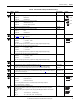
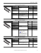
I/O Wiring Examples
Input/Output Connection Example Required Parameter Changes
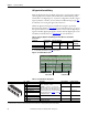
Potentiometer Unipolar Speed
Reference
10kΩ Pot. Recommended
(2kΩ Minimum)
• Adjust Scaling:
72 [Anlg In1 Scale] and
73 [Anlg1 Tune Scale]
• View Signal Value:
1404 [Analog In1 Value]
• View Signal Output:
385 [Speed Ref Out]
Note: DIP switch S9 should be set to
“On” (0…10V). See Table 26
on
page 54.
Joystick Bipolar Speed
Reference
±10V Input
Important: See the Attention
statement on page 77
for important
bipolar wiring information.
• Set Direction Mode:
1322 [Direction Mode]
= 1 “Bipolar”
• Adjust Scaling:
72 [Anlg In1 Scale] and
73 [Anlg1 Tune Scale]
• View Signal Value:
1404 [Analog In1 Value]
• View Signal Output:
385 [Speed Ref Out]
Note: DIP switch S9 should be set to
“On” (0…10V). See Table 26
on
page 54.
Analog Input Bipolar Speed
Reference
±10V Input
Important: See the Attention
statement on page 77 for important
bipolar wiring information.
• Set Direction Mode:
1322 [Direction Mode]
= 1 “Bipolar”
• Adjust Scaling:
72 [Anlg In1 Scale] and
73 [Anlg1 Tune Scale]
• View Signal Value:
1404 [Analog In1 Value]
• View Signal Output:
385 [Speed Ref Out]
Note: DIP switch S9 should be set to
“On” (0…10V). See Table 26
on
page 54.
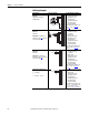
Analog Input Unipolar Speed
Reference
0…+10V Input
or
0…20 mA or 4…20 mA
• Configure for Voltage or Current:
71 [Anlg In1 Config]
• Adjust Scaling:
72 [Anlg In1 Scale] and
73 [Anlg1 Tune Scale]
• View Signal Value:
1404 [Analog In1 Value]
• View Signal Output:
385 [Speed Ref Out]
Note: DIP switch S9 should be set to
“On” for 0…10V operation, or “Off”
for 0…20 mA or 4…20 mA
operation. See Tabl e 26
on page 54.
1
2
3
4
5
6
7
8
9
10
1
2
3
4
5
6
7
8
9
10
Common
+
1
2
3
4
5
6
7
8
9
10
Common
+
1
2
3
4
5
6
7
8
9
10