
Owner's manual

Rockwell Automation Publication 20P-UM001I-EN-P - February 2013 79
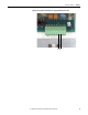
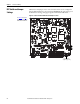
Installation and Wiring Chapter 1
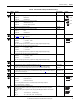
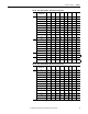
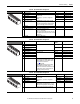
Table 34 - I/O Terminal Block 2 Designations
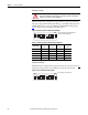
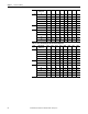
Table 35 - I/O Terminal Block 3 Designations
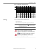
Table 36 - I/O Terminal Block 4 Designations
No. Signal Description Factory Default Config. Parameter
11 Internal 0V (Gnd) – –
12 Digital Input 1 Max +30V, 15V/3.2 mA, 24V/5 mA,
and 30V/6.4 mA.
A digital input (1…8) must be configured for
“Enable”.
2 “Stop/CF” 133 [Digital In1 Sel]
13 Digital Input 2 3 “Start” 134 [Digital In2 Sel]
14 Digital Input 3 11 “Jog” 135 [Digital In3 Sel]
15 Digital Input 4 1 “Enable” 136 [Digital In4 Sel]
16 Digital Input Common Important: When using the internal +24V DC
supply (terminal 19) for digital inputs 1…4, you
must connect the digital input common (terminal
16) to the +24V supply common (terminal 18).
––
17 Not Used – –
18 24V Supply Common Common for the internal power supply. – –
19 Internal +24V DC Supply Drive supplied +24V DC I/O power.
Max. +20…30V, 200 mA
Note: The total current draw is the sum of encoder
power, digital outputs and any other loads connected
to terminal 19.
––
20 PE ground PE ground to drive chassis. – –
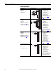
12
13
14
15
11
17
18
19
20
16
No. Signal Description Factory
Default
Config. Parameter
21 Analog Output 1 (+) Max. ±10V, 5 mA. 12 “Motor Speed” 66 [Anlg Out1 Sel]
22 Analog Output 1 (–)
23 Analog Output 2 (+) 13 “Motor Curr” 67 [Anlg Out2 Sel]
24 Analog Output 2 (–)
25 Digital Output Common – –
26 Digital Output 1 Max. +30V, 50 mA 5 “Ready” 145 [Digital Out1 Sel]
27 Digital Output 2 9 “Fault” 146 [Digital Out2 Sel]
28 Digital Output 3 2 “Spd Thresh” 147 [Digital Out3 Sel]
29 Digital Output 4 4 “CurrentLimit” 148 [Digital Out4 Sel]
30 Digital Output +24VDC Source Tie point for the internal supply or customer
supplied voltage for the digital outputs. See the
I/O Wiring Examples for sourcing digital outputs
on page82
for more information.
Max. +30V DC, 80 mA.
Important: When using the internal +24V DC
supply (terminal 19) for digital outputs 1…4,
you must connect terminal 19 to terminal 30 and
the digital output common (terminal 25) to the
+24V supply common (terminal 18).
––
22
23
24
25
21
27
28
29
30
26
No. Signal Description Factory Default Config. Parameter
31 Digital Input 5 Max +30V, 15V/3.2 mA, 24V/5 mA,
and 30V/6.4 mA.
A digital input (1…8) must be configured for
“Enable”.
17 “Speed Sel 1” 137 [Digital In5 Sel]
32 Digital Input 6 18 “Speed Sel 2” 138 [Digital In6 Sel]
33 Digital Input 7 19 “Speed Sel 3” 139 [Digital In7 Sel]
34 Digital Input 8 31 “Contactor” 140 [Digital In8 Sel]
35 Digital Input Common Important: When using the internal +24V DC
supply (terminal 19) for digital inputs 5…8, you
must connect the digital input common (terminal
35) to the +24V supply common (terminal 18).
––
36
…
40
Not Used – –
32
33
34
35
31
37
38
39
40
36