
Owner's manual

70 Rockwell Automation Publication 20P-UM001I-EN-P - February 2013
Chapter 1 Installation and Wiring
Frame C and D Armature Fuse Signal Terminals
Terminals 81 and 82 on frame C and D drives are connected to the internal
armature circuit protection fuses and can be connected to an external device to
provide indication that the fuses have opened. Alternatively, terminals 81 and 82
can be wired to drive digital input terminals configured for 64 “Invert Flt” (via
Pars 133…144).
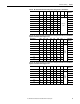
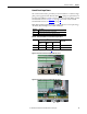
Table 24 - Armature Fuse Signal Terminal Designations
Table 25 - Armature Fuse Signal Wire Size and Terminal Specifications
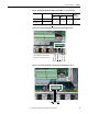
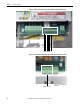
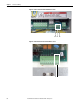
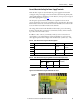
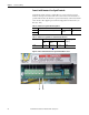
Figure 47 - Frame C Internal Armature Fuse Signal Terminal Block Location
Terminal Description Maximum Voltage Maximum Current
81 Internal armature fuse intervention signal.
250V AC 1 A
82
Terminals Wire Size and Type
(1)
(1) See Cable and Wiring Recommendations on page 44 for more information.
Tightening Torque
N•m (lb•in)
Flexible
(mm
2
)
Multi-core
(mm
2
)
AWG
81, 82 0.14…1.5 0.14…2.5 26…16 0.4 (3.5)
81 82