
Owner's manual

68 Rockwell Automation Publication 20P-UM001I-EN-P - February 2013
Chapter 1 Installation and Wiring
Frame C Heatsink Cooling Fans Power Supply Terminals
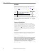
Frame C drives require an external 230V AC power supply for the heatsink
cooling fans. The power supply connections must be taken from the primary side
of the installed Isolation Transformer or Line Reactor (clean power). See Typical
Power Wiring Diagrams on page 46
.
In addition, the fan power input terminals U3 and V3 are required to be short
circuit protected. This protection can be provided by using a circuit breaker. The
circuit breaker must be selected to survive the short circuit available current of
the feeder source for this circuit and the inrush current of the fan.
The rating of the circuit breaker should be sized mainly to protect the wiring
from the circuit breaker connections to terminals U3 and V3, and not nuisance
trip or blow from the inrush current.
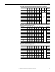
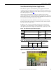
Table 20 - Frame C Heatsink Cooling Fans Terminal Designations
Table 21 - Frame C Heatsink Cooling Fans Wire Sizes and Terminal Specifications
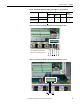
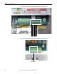
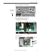
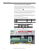
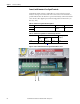
Figure 45 - Frame C Heatsink Cooling Fan Terminal Block Location
Terminal Description Maximum Voltage Maximum Current
U3 Single-phase AC input power for cooling fans.
230V AC 1 A
V3
Terminals Wire Size and Type
(1)
(1) See Cable and Wiring Recommendations on page 44 for more information.
Tightening Torque
N•m (lb•in)
Flexible
(mm
2
)
Multi-core
(mm
2
)
AWG
U3, V3 0.14…1.5 0.14…2.5 26…16 0.4 (3.5)
U3 V3