
Owner's manual

Rockwell Automation Publication 20P-UM001I-EN-P - February 2013 65
Installation and Wiring Chapter 1
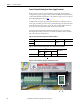
Control Circuit Input Power
The control circuit must be powered by an external 230V AC or 115V AC single
phase power supply. For frame B and C drives only
, a jumper is required between
terminals SA and SB for 115V AC control input power. For frame B drive SA-SB
terminal block location, see Figure 43
on page 67. For frame C drive SA-SB
terminal block location, see Figure 43
on page 67.
Note: If the SA-SB terminal block is not configured for the correct input voltage,
“No Fault” (F0) will display on the HIM, if installed.
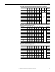
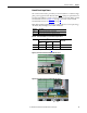
Table 19 - Control Circuit Wire Sizes and Terminal Specifications
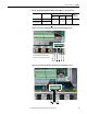
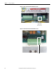
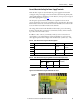
Figure 39 - Frame A Control Circuit Terminal Block Location
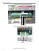
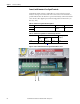
Figure 40 - Frame B Control Circuit Terminal Block Location
Terminals Description
U2, V2 Single phase AC power for the control circuits
PE Safety ground (on frame C drive terminal blocks only)
Terminals Wire Size and Type
(1)
(1) See Cable and Wiring Recommendations on page 44 for more information.
Tightening Torque
N•m (lb•in)
Flexible
(mm
2
)
Multi-core
(mm
2
)
AWG
U2, V2 0.14…1.5 0.14…2.5 26…14 0.5 (4.4)
PE 2.5…10 2.5…10 12…8 2.0 (18.0)
U2 V2
U2 V2