
Owner's manual

Rockwell Automation Publication 20P-UM001I-EN-P - February 2013 63
Installation and Wiring Chapter 1
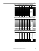
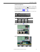
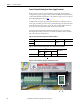
Table 18 - Relay Outputs and Thermistor/Thermal Switch Wire Sizes and Specifications
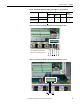
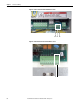
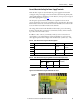
Figure 35 - Frame A Relay and Thermistor/Thermal Switch Terminal Block Locations
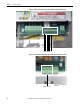
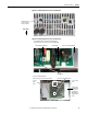
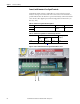
Figure 36 - Frame B Relay and Thermistor/Thermal Switch Terminal Block Locations
Signal Type Terminals Wire Size and Type
(1)
(1) See Cable and Wiring Recommendations on page 44 for more information.
Tightening
Torque
N•m (lb•in)
Flexible
(mm
2
)
Multi-core
(mm
2
)
AWG
Relay Outputs 35 & 36, 75 & 76
0.140…1.500 0.140…1.500 26…14 0.5 (4.4)
Thermistor and
Thermal Switches
78 & 79
78 79 35 36 75 76
Note: Terminals 78 and 79 shown with 1
kΩ resistor in place of temperature sensor.
78 79 35 36 75 76