
Owner's manual

48 Rockwell Automation Publication 20P-UM001I-EN-P - February 2013
Chapter 1 Installation and Wiring
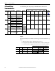
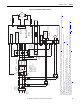
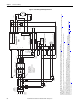
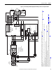
Figure 20 - Power Wiring with DC Output Contactor
C
D
PowerFlex DC
Drive
36
(7)
34
(4)
(on I/O TB4)
19
(5)
(+24V on I/O TB2)
Control
Board P/S
115V
or
230V
(1)
V2
U2
F2
35
(7)
U
V
W
3 Phase
AC line
L1
L2
L3
U1
V1
C1
D1
F1
FS1
(3)
FS1
(3)
FS1
(3)
FU1
FV1
FU FU
Field Power Terminal Block
Control Power / Relay Outputs
Terminal Block
A1
A2
Armature Volt.
Fdbk. Term.
1A1
1A2
U3
V3
Fan Power Terminal Block
(8)
230V
FU FU
Line Reactor
(2)
Lockable
Installation
Disconnect
SB
(1)
SA
(1)
M
Aux
(N.O. Relay)
M1 DC
Contactor
A1
A2
13 14
L1
L2
A1
T1
T2
A2
FS2
(6)
FS2
(6)
These connections
must be taken from
the primary side of
the Isolation Transformer
or Line Reactor
(clean power).
AC Input
Voltage
AC Input
Voltage
Isolation
Transformer
(2)
Safety Ground
PE
AC Input
Voltage
460 VAC
Max. or
230 VAC
Min.
(9)
(1) For frame B and C drives only, a jumper is required between terminals SA and SB for 115V AC control input power. See Control Circuit Input Power on page 65 for more information.
(2) An Isolation Transformer and/or 3…5% impedance Line Reactor is required. If the Isolation Transformer provides the required 3…5% impedance, a Line Reactor is not required. See AC Input Line Reactors and AC Input Contactors on page 238
and Isolation Transformers on page 241 for
recommendations.
(3) AC input fuses for the armature converter are customer supplied for frame A and B drives and are internally mounted on frame C and D drives. See Drive Power Circuit Protection on page 219
for fuse recommendations.
(4) Par 140 [Digital In8 Sel] set to 31 “Contactor”
(5) If using the +24V internal power supply, terminal 18 (24V common) must be jumpered to terminal 35 (digital input common).
(6) Customer supplied armature output fuses are required on four quadrant and are recommended on two quadrant Frame A and B drives. See Drive Power Circuit Protection on page 219
for fuse recommendations.
(7) Par 1391 [ContactorControl] = 3 “DC Cntctr” and Par 1392 [Relay Out 1 Sel] = 25 “Contactor”. Important: Terminal 35 and 36 are on the Control Power / Relay Outputs Terminal block, NOT the I/O terminal blocks. See Figure 35
on page 63…Figure 37 on page 64.
(8) Frame C & D drives only require an external power supply for the heatsink cooling fan. See Frame C Heatsink Cooling Fans Power Supply Terminals on page 68
and Frame D Heatsink Cooling Fan Power Supply Terminals on page 69 for more information.
(9) See Field Converter Connections on page 56
.