
Owner's manual

Rockwell Automation Publication 20P-UM001I-EN-P - February 2013 43
Installation and Wiring Chapter 1
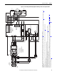
Power Circuit Protection
It is recommended that you install frame A and B PowerFlex DC drives with fast
acting fuses to protect the armature converter on the AC input and DC output
(for four quadrant drives only) sides. Internally mounted fuses for armature
converter protection are provided with frame C and D PowerFlex DC drives. See
Drive Power Circuit Protection on page 219
for a list of replacement fuses and
general fuse locations.
Control Power Protection
The 115V / 230V AC control circuit power input terminals U2 and V2 are
required to be short circuit protected. This protection can be provided by using
standard time delay fuses or a circuit breaker. The time delay fuses or circuit
breaker must be selected to survive the short circuit available current of the feeder
source for this circuit and the inrush current of the drive’s power supply.
The rating of the fuses or circuit breaker should be sized mainly to protect the
wiring from the fuses/circuit breaker connections to terminals U2 and V2, and
not nuisance trip or blow from the inrush current.
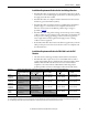
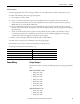
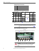
The table below lists the input current characteristics of the control power.
Table 9 - Control Power Protection
Control power input should be supplied by a power source that is stabilized and
buffered from the power system transients. The control power of many drives can
be fed from a single source, as long as proper distribution protection is provided.
Frame Control Power Supply
Circuit Board ID / Revision Power Rated input current Inrush input current
115V AC 230V AC 115V AC 230V AC
A & D SW1-31 / H & below 60 W 1 A 0.5 A 20 A 10 A
SW1-31 / I & above 80 W 1 A 0.5 A 6 A 10 A
B SW2-32 / H & below 110 W 1.2 A 0.7 A 15 A 7.5 A
SW2-32 / I & above 90 W 1.2 A 0.6 A 6 A 10 A
C SW3-32 / H & below 110 W 1.2 A 0.7 A 15 A 7.5 A
SW3-32 / I & above 90 W 1.2 A 0.6 A 6 A 10 A