
Owner's manual

38 Rockwell Automation Publication 20P-UM001I-EN-P - February 2013
Chapter 1 Installation and Wiring
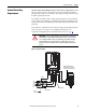
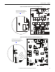
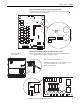
Figure 15 - Frame C Pulse Transformer Circuit Board S9 Jumper Location
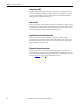
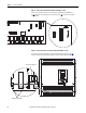
Figure 16 - Frame C Transient Noise Filter Circuit Board Ground Wire Location
X3
XCD_IO
TO5
TO3
TO6
TO2
O4
KGO2
KGO5
KGO3 KGO6
T5 T3
T6
T2
KG2
KG5
KG3
KG6
XCT
PE
PE1
XCD
S3
S4
XUVW
1
1
XTA
TR3
XR
S9
XCD_IO
PE
PE1
XCD
S9
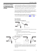
Note: The pulse transformer circuit board is located at the top of the drive behind the control EMI shield. See
page 29
for instructions on removing the front covers from the drive and page 67 for instructions on moving the
control EMI shield.
STS
PORT
MOD
NET A
NET B
U
V
C
Yellow/Green (Ground) Wire
Transient Noise Filter Board
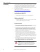
Note: Remove the Front Covers from the Drive to Access the Transient Noise Filter Circuit Board. See page 29 for
instructions. The Transient Noise Filter Board Located Between Terminals C and D below the Control EMI Shield.