
Owner's manual

Rockwell Automation Publication 20P-UM001I-EN-P - February 2013 37
Installation and Wiring Chapter 1
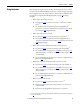
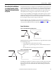
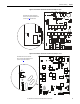
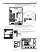
Figure 13 - Frame A Pulse Transformer Circuit Board S9 Jumper Location
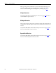
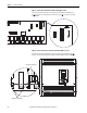
Figure 14 - Frame B Pulse Transformer Circuit Board S9 Jumper Location
S9
T01 T04 T02 T05
T03
T06
T1 T4 T2 T5 T3 T6
78 79 35 36 75 76 U2 V2
S4
S3
XY
XR
TR2 TR1
XP
XSW
XSW1
X3
X4
S9
Note: Remove the front covers from the
drive to access the pulse transformer circuit
board. See page 28 for instructions.
S9
PE
XCD_IO
XTA
78 79 35 36 75 76 U2 V2
T01
T4
T1
T2
T02
T5
T3
T6
T03
T06
T04
T05
TR1
TR2
S9
PE
Note: Remove the front covers from the
drive to access the pulse transformer circuit
board. See page 29
for instructions.