
Owner's manual

36 Rockwell Automation Publication 20P-UM001I-EN-P - February 2013
Chapter 1 Installation and Wiring
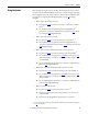
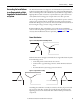
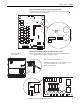
Figure 12 - High Resistance Ground
Grounding the wye secondary neutral through a resistor is an acceptable method
of grounding. Under a short circuit secondary condition, any of the output
phases to ground will not exceed the normal line to line voltage. The resistor is
often used to detect ground current by monitoring the associated voltage drop.
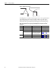
Table 8 - Drive Modifications to Support Ungrounded Wye Neutral or Impedance Grounded
Connections
Frame Circuit Board Jumper/Connection Figure to see for Details
APulse Transformer (FIR1-xx-xx) Remove jumper S9 Figure 13
on page 37
BPulse Transformer (FIR2-xx-xx) Remove jumper S9 Figure 14 on page 37
CPulse Transformer (FIR3-xx-xx) Remove jumper S9 Figure 15 on page 38
Transient Noise Filter (FIL-31) Disconnect the filter board yellow/
green (ground) wire from the PE
connection on the drive chassis
Figure 16 on page 38
D Pulse Transformer (FIR-D-xx-xx) Remove capacitors C121 and C122 Figure 17 on page 39
Overvoltage Clipping (CFSF-xxx) Remove jumper S1 Figure 18 on page 39