
Owner's manual

Rockwell Automation Publication 20P-UM001I-EN-P - February 2013 219
Supplemental Drive Information Appendix A
Drive Power Circuit
Protection
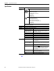
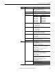
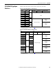
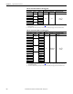
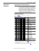
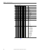
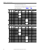
The tables on the following pages provide the recommended fuses for protecting
the armature and field circuits of the drive. Externally mounted fuses (as
indicated in Figure 62
below) must be sourced separately when installing the
drive. Internally mounted fuses (as indicated in Figure 62
below and Figure 65 on
page 225
) are provided with the drive.
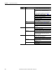
See page 225
for frames C and D fuse information.
Frame A and B Fuse Information
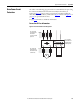
Figure 62 - Frame A and B Fuse Table Designations
FS1
FS2
M
U V W
C D
FS3
C1 D1
U1 V1
FS1 = Externally
mounted fuses for
the armature
converter on the AC
input side.
FS2 = Externally
mounted fuses for
the armature circuit
on the DC side.
FS3 = Internally
mounted fuses for
the field circuit on
the AC input side.