
Owner's manual

214 Rockwell Automation Publication 20P-UM001I-EN-P - February 2013
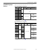
Appendix A Supplemental Drive Information
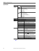
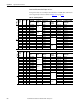
Category Specification
Feedback
Devices
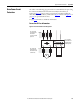
Encoder Type: Incremental, dual channel, two channel optional (with
jumper), differential (recommended) or single-ended
Input Voltage: Configurable for +2.5V…5.2V (switch S21 in
ENC_5 position) or +5.4V…15.2V (switch S21 in ENC_12
position).
Note: The encoder must be capable of the same power supply
(input) and feedback level (output) voltage (see page 73).
Input Current: 3 mA…10.9 mA each channel
Quadrature: 90° ± 27° @ 25°C
Duty cycle: 50% ± 10% Source/Sink capable
Pulses Per Revolution: 100…32770
Maximum Frequency: 150 kHz
Maximum Cable Length: Shielded, 150m (0.75 mm
2
), 125m (0.5
mm
2
), 55m (0.22 mm
2
)
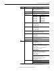
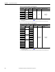
Resolver See the PowerFlex DC Drive Resolver Feedback Option Module
Installation Instructions, publication 20P-IN071 for details.
DC Analog Tachometer Input Voltage: 22.7, 45.4, 90.7, 181.6, & 302.9V max.
Input Current: 8 mA full scale
Maximum Cable Length: Shielded, depends on the installation,
typical 150 m.
Inputs Analog Inputs Three configurable, isolated, differential
±10V, 0-10V, 0-20 mA or 4-20 mA.
Resolution: 11 Bit + sign
Digital Inputs Eight standard configurable, four additional configurable with the
I/O Expansion circuit board.
Max Voltage +30V DC input, 200 mA (total current draw is the
sum of encoder power, digital outputs and any other loads
connected to terminal 19)
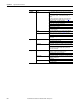
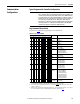
Outputs Analog Outputs Two standard configurable, two additional configurable with the
I/O Expansion circuit board. Sampling rate 2 ms.
± 10V, 5mA, bipolar (current is not bipolar)
Resolution: 11 Bit + sign
Digital Outputs Four standard configurable, four additional configurable with the
I/O Expansion circuit board.
+ 30V, 50 mA
Relay Outputs Two configurable, N.O. contacts
Max. 250V AC, 1A AC1