
Owner's manual

206 Rockwell Automation Publication 20P-UM001I-EN-P - February 2013
Chapter 4 Troubleshooting
Clearing Alarms
Alarms are automatically cleared when the condition that caused the alarm is no
longer present.
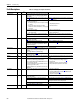
Alarm Descriptions
The status of the alarms can be viewed in 1380 [Drive Alarm 1].
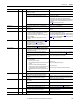
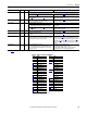
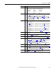
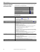
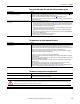
Table 41 - Alarm Descriptions and Actions
Alarm Type Description
Arm Overvoltage 1 There is a possible overvoltage on the armature circuit or Par 175
[Rated Motor Volt] is set too
low for the application. See the “Arm Overvoltage” fault description on page 202 for more
information.
Auxiliary Input 1 An auxiliary input interlock is open or a voltage (+15 - 30 V) or reference signal is missing for
the digital input set to 14 “Aux Fault”. See the “Auxiliary Input” fault description on page 202
for more information.
BipolarCflct 2 Par 1322
[Direction Mode] is set to “Bipolar” or “Reverse Dis” and one or more of the
following digital input functions is configured: “Fwd/Reverse,” “Run Forward,” “Run
Reverse,” “Jog Forward” or “Jog Reverse.”
CntactrCflct 2 Contactor input functions are in conflict:
• When Par 1391
[ContactorControl] is set to “None”, both relay outputs (Pars 1392 [Relay
Out 1 Sel] and 629 [Relay Out 2 Sel] and all digital inputs ([Digital Inx Sel]) cannot be set
to “Contactor” or “ContactorDB”.
• With [ContactorControl] set to “AC Cntcr” or “DC Cntcr”, one relay output and one digital
input must be set to “Contactor”. No relay or digital output can be defined as
“ContactorDB”.
• With [ContactorControl] set to “AC Cntcr+DB” or “DC Cntcr+DB”, both relay outputs and
one digital input must be set to “Contactor”, “ContactorDB” and “Contactor”, respectively.
Because any relay output can be configured as contactor or DB control and any digital input
as contactor status, care must be taken to correctly wire the terminal blocks to match the
parameter selections.
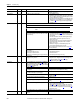
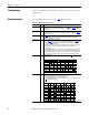
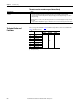
DigInCflctA 2 Digital input functions are in conflict. Combinations marked with a “ ” will cause an alarm.
DigInCflctB 2 One of the following digital input conflicts exists:
• A digital Start input has been configured without a Stop input
• None of the digital inputs are configured for “Enable”
• Other digital input functions are in conflict. Combinations that conflict are marked with a
“ ” and will cause an alarm.
Acc2/Dec2 Accel 2 Decel 2 Jog 1/2 Jog Fwd Jog Rev Fwd/Rev
Acc2/Dec2
Accel 2
Decel 2
Jog 1/2
Jog Fwd
Jog Rev
Fwd/Rev
Start
Stop-
CF Run Run Fwd Run Rev
Jog
1/2 Jog Fwd Jog Rev
Fwd/
Rev
Start
Stop-CF
Run
Run Fwd
Run Rev
Jog 1/2
Jog Fwd
Jog Rev
Fwd/Rev