
Owner's manual

Rockwell Automation Publication 20P-UM001I-EN-P - February 2013 17
Chapter 1
Installation and Wiring
This chapter provides information on mounting and wiring the PowerFlex DC
drive.
Most start-up difficulties are the result of incorrect wiring. Every precaution must
be taken to assure that the wiring is done as instructed. All items must be read and
understood before the actual installation begins.
For PowerFlex DC Standalone Regulator (SAR) installations, see Appendix H
for important installation and configuration information. The SAR is identified
by a 23PMDx catalog number contained on the data nameplate on the drive (see
Drive Nameplate Data on page 12
for location).
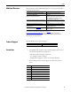
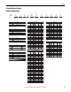
Topic Page Topic Page
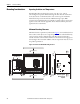
Mounting Considerations 18 CE Conformity 40
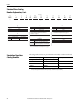
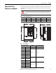
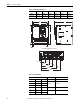
Approximate Drive Dimensions and
Weights
19 Power Circuit Protection 43
Lifting PowerFlex DC Drives 25 Control Power Protection 43
Removing the Drive Covers 28 Cable and Wiring Recommendations 44
Isolation Transformers / Line Reactors 30 Power Wiring 45
Using Contactors 31 DIP Switch and Jumper Settings 72
General Grounding Requirements 33 I/O Wiring 77
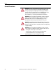
IMPORTANT
The PowerFlex DC drive is not designed for use with multiple motor
applications or resistive loads.
IMPORTANT
The drive to motor horsepower ration must not exceed 2:1.
ATTENTION: The following information is merely a guide for proper installation.
Rockwell Automation cannot assume responsibility for the compliance or the
noncompliance to any code, national, local or otherwise for the proper
installation of this drive or associated equipment. A hazard of personal injury
and/or equipment damage exists if codes are ignored during installation.