
Owner's manual

Rockwell Automation Publication 20P-UM001I-EN-P - February 2013 161
Programming and Parameters Chapter 3
APPLICATIONS
Winder Functions
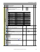
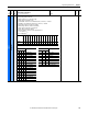
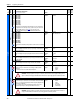
1284 [Ref Spd Source]
Parameter number from which the line speed reference (used for inertia
compensation and line speed reference) will be read.
Notes: Added options 0…47 for firmware version 4.001. Added option 48
“Resolver Spd” for firmware version 5.002.
Default: 0 = “Not Used” 16-bit
Int
Options:
1285 [Ref Speed Gain]
Gain value for the line speed reference. The value of this parameter depends on the
value of Par 1284 [Ref Spd Source]. The value of [Ref Speed Gain] is used to obtain
a line speed reference = 100% at its maximum value.
Default:
Min/Max:
0
0 / 32767
16-bit
Int
1284
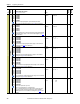
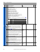
1286 [Ref Line Speed]
Line speed percentage.
Default:
Min/Max:
Units:
Read Only
0.00 / 150.00
%
Real
1287 [Static F Zero]
Enables/Disables friction compensation.
• "Enabled" = The fiction compensation value is added to all speed values.
• "Disabled" = The static friction compensation value is added to Par 1286 [Ref
Line Speed] = 1.5%.
Default:
Options:
0 =
0 =
1 =
“Disabled”
“Disabled”
“Enabled”
16-bit
Int
1286
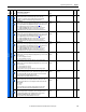
Scale Blocks
484
553
1218
1227
1236
1245
[Scale1 Input]
[Scale2 Input]
[Scale3 Input]
[Scale4 Input]
[Scale5 Input]
[Scale6 Input]
Parameter number from which the value is read and used as the input quantity to
the Scale block. See the Scale Blocks block diagram on page 331
for more
information.
Default:
Min/Max:
0
0 / 1410
16-bit
Int
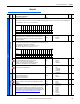
485
554
1219
1228
1237
1246
[Scale1 Output]
[Scale2 Output]
[Scale3 Output]
[Scale4 Output]
[Scale5 Output]
[Scale6 Output]
Parameter number to which the value of the Scale block output is written. See the
Scale Blocks block diagram on page 331
for more information.
Default:
Min/Max:
0
0 / 1410
16-bit
Int
File
Group
No.
Parameter Name & Description
See page 110 for symbol descriptions
Values
Data Type
Related
A
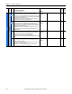
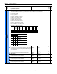
0 = “Not Used” 17 = “Max Fld Pct” (Par 467) 34 = “UsrDefined15” (Par 518)
1 = “Cur Lim Pos” (Par 8) 18 = “Fld Ref Pct” (Par 500) 35 = “Load Comp” (Par 698)
2 = “Cur Lim Neg” (Par 9) 19 = “UsrDefined0” (Par 503) 36 = “Out Volt Lvl” (Par 921)
3 = “CurLimPosOut” (Par 10) 20 = “UsrDefined1” (Par 504) 37 = “Filt Trq Cur” (Par 928)
4 = “CurLimNegOut” (Par 11) 21 = “UsrDefined2” (Par 505) 38 = “Speed Ratio” (Par 1017)
5 = “TrqRedCurLim” (Par 13) 22 = “UsrDefined3” (Par 506) 39 = “Spd Draw Out” (Par 1018)
6 = “Torque Ref” (Par 39) 23 = “UsrDefined4” (Par 507) 40 = “Roll Diam” (Par 1154)
7 = “Trim Torque” (Par 40) 24 = “UsrDefined5” (Par 508) 41 = “Tension Red” (Par 1179)
8 = “TorqueReg In” (Par 41) 25 = “UsrDefined6” (Par 509) 42 = “Torq Cur Pct” (Par 1193)
9 = “Trim Ramp” (Par 42) 26 = “UsrDefined7” (Par 510) 43 = “Ten Ref Pct” (Par 1194)
10 = “Trim Speed” (Par 43) 27 = “UsrDefined8” (Par 511) 44 = “CloseLp Comp” (Par 1208)
11 = “Ramp In” (Par 110) 28 = “UsrDefined9” (Par 512) 45 = “Actual Comp” (Par 1213)
12 = “Ramp Out” (Par 113) 29 = “UsrDefined10” (Par 513) 46 = “W Reference” (Par 1217)
13 = “Speed Reg In” (Par 118) 30 = “UsrDefined11” (Par 514) 47 = “Encoder Spd” (Par 420)
14 = “Adaptive Ref” (Par 183) 31 = “UsrDefined12” (Par 515) 48 = “Resolver Spd” (Par 428)
15 = “Arm Cur Pct” (Par 199) 32 = “UsrDefined13” (Par 516)
16 = “SpdRegOutPct” (Par 236) 33 = “UsrDefined14” (Par 517)
A
A
A
A
A