
Owner's manual

152 Rockwell Automation Publication 20P-UM001I-EN-P - February 2013
Chapter 3 Programming and Parameters
APPLICATIONS
PD Control
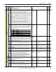
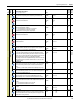
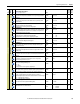
768 [PD Prop Gain 1]
First proportional gain of the block PD. The value specified in this field depends on
the enabling and configuration of Par 181 [Adaptive Spd En].
Default:
Min/Max:
10.00
0.00 / 100.00
Real 181
770 [Enable PD]
Enables/disables the PD portion of the PID regulator.
Note: This parameter can be assigned to a digital input.
Default:
Options:
0 =
0 =
1 =
“Disabled”
“Disabled”
“Enabled”
16-bit
Int
788 [PD Prop Gain 2]
Second proportional gain of the block PD. The value specified in this field depends
on the enabling and configuration of Par 181 [Adaptive Spd En].
Default:
Min/Max:
10.0
0.0 / 100.0
Real 181
789 [PD Deriv Gain 2]
Second derivative gain of the PD block. The value specified in this field depends on
the enabling and configuration of Par 181 [Adaptive Spd En].
Default:
Min/Max:
10.0
0.0 / 100.0
Real 181
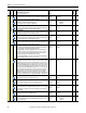
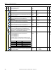
790 [PD Prop Gain 3]
Third proportional gain of the block PD. The value specified in this field depends on
the enabling and configuration of Par 181 [Adaptive Spd En].
Default:
Min/Max:
10.0
0.0 / 100.0
Real 181
791 [PD Deriv Gain 3]
Third derivative gain of the PD block. The value specified in this field depends on
the enabling and configuration of Par 181 [Adaptive Spd En].
Default:
Min/Max:
1.00
0.00 / 100.00
Real 181
PID Control
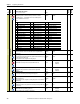
418 [Real FF PID]
Represents the feed–forward value which has been recalculated according to the
PI correction. It will be calculated with the following formula:
Par 418 [Real FF PID] = (Par 758 [Feed Fwd PID] / 1000 ) x Par 771 [PI Output]
When either the negative or positive limit of this parameter has been reached,
further increases in the value of Par 771 [PI Output] will be blocked in order to
avoid undesirable saturation of the PID regulator. For example:
When Par 758 [Feed Fwd PID] = +8000, the positive limit of Par 771 [PI Output]
will be automatically set at 10000 / ( 8000 / 1000 ) = 1250.
Default:
Min/Max:
Read Only
–/+10000
16-bit
Int
758,
771
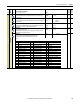
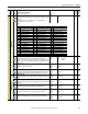
757 [PID Clamp]
The PID “clamp” allows a smooth tension setting of a controlled system winder/
unwinder when the calculation of the initial diameter function cannot be used.
• When enabling the drive, the dancer is at the lowest point of its full scale. In this
case, with Par 759 [PID Error] at its maximum value, the motor could accelerate
too fast to properly configure the dancer for its central operating position. By
setting the value of Par 757 [PID Clamp] sufficiently low. e.g, = 1000, when the
drive starts and Par 770 [Enable PD] = 1 “Enable”, the value of Par 759 [PID
Error] is limited to 1000 until the signal coming from the dancer (via Par 763
[PID Feedback]) goes above the value in this field. Then, the value of [PID
Clamp] is automatically returned to its maximum value of 10000. The PID clamp
is kept at 10000 until the drive stops or Par 770 [Enable PD] = 0 “Disabled”.
Default:
Min/Max:
10000
0 / 10000
16-bit
Int
759,
763,
770
758 [Feed Fwd PID]
Feedback from the transducer position (dancer) or tension.
Default:
Min/Max:
Read Only
–/+10000
16-bit
Int
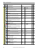
759 [PID Error]
Error value input to the PID function (output of the PID Clamp block).
Default:
Min/Max:
Read Only
–/+10000
16-bit
Int
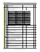
760 [PID Setpoint 0]
First offset value added to Par 763 [PID Feedback]. This parameter can be assigned
to an analog input, for example, for the tension setting when a load cell must be
used as feedback.
Default:
Min/Max:
0
–/+10000
16-bit
Int
763
761 [PID Setpoint 1]
Second offset value added to Par 763 [PID Feedback].
Default:
Min/Max:
0
–/+10000
16-bit
Int
763
762 [PID Setpoint Sel]
Selects the offset value added to Par 763 [PID Feedback]. This parameter can be
assigned to a digital input.
Default:
Options:
0 =
0 =
1 =
“Setpoint 0”
“Setpoint 0”
“Setpoint 1”
16-bit
Int
763
File
Group
No.
Parameter Name & Description
See page 110 for symbol descriptions
Values
Data Type
Related
A
A
A
A
A
A
A
A
A
A
A
A