
Manual

Publication 20P-IN062A-EN-P
2
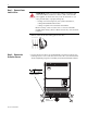
Step 1: Remove Power
from the Drive
• Remove and lock-out all incoming power to the drive.
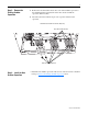
Step 2: Remove the
Protective Covers
• Loosen, but do not remove, the ten hexalobular screws that secure the two
bottom protective covers to the drive, then remove the covers from the drive
chassis. Tightening torque for reassembly is noted in the illustration below.
ATTENTION: Remove power before making or breaking cable
connections. When you remove or insert a cable connector with
power applied, an electrical arc may occur. An electrical arc can
cause personal injury or property damage by:
• sending an erroneous signal to your system’s field devices,
causing unintended machine motion
• causing an explosion in a hazardous environment
Electrical arcing causes excessive wear to contacts on both the
module and its mating connector. Worn contacts may create electrical
resistance.
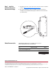
L1 L2 L3
O
I
Bottom
protective cover
Tightening torque:
1.5 N•m (13 lb•in)
T15