
User Manual

4 Rockwell Automation Publication 20P-IN072A-EN-P - October 2013
PowerFlex DC Drive - Frame D, Series B Fan Circuit Board
Step 3: Remove the Existing
Fan Circuit Board
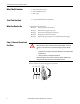
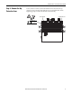
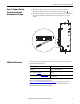
1. Remove the plug-in terminal block TB1 at XF2 from the fan circuit board.
2. Remove the plug-in terminal block TB2 at XF from the fan circuit board.
3. Remove the plug-in terminal block TB3 at XE from the fan circuit board.
4. Disconnect the ground wire from connector PE.
5. Remove the four hexalobular screws that secure the fan circuit board to the
insulator and remove the board. Tightening torque is noted in the
illustration for reassembly.
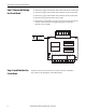
Step 4: Install the New Fan
Circuit Board
Install the new fan circuit board in reverse order of removal as detailed in
Step 3: Remove the Existing Fan Circuit Board above.
32 31 PE W3 V3 U3
TB3
TB1TB2
PE
TB TB PE W3F V3F U3F Z3F Y3F X3F
XF XF2
XE
Tool size: T25
1.0…1.2 N•m
(9…10.5 lb•in)