
Owner manual

2 Rockwell Automation Publication 20P-IN052B-EN-P - October 2013
PowerFlex DC Drive - Frame D, Series A Fan Circuit Board
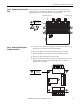
What This Kit Includes
• Fan loss detection circuit board (series A)
• Four hexalobular screws
• Static strap
Tools That You Need
• T15 and T25 hexalobular screwdrivers
What You Need to Do
To install the fan loss detection board:
❐ Step 1: Remove power from the drive
❐ Step 2: Remove the top protective cover
❐ Step 3: Remove the existing fan loss detection board
❐ Step 4: Install the new fan loss detection board
❐ Step 5: Replace the top protective cover and document the change
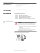
Step 1: Remove Power from the
Drive
Remove and lock-out all incoming power to the drive.
ATTENTION: Remove power before making or breaking cable connections.
When you remove or insert a cable connector with power applied, an electrical
arc may occur. An electrical arc can cause personal injury or property damage
by:
• sending an erroneous signal to your system’s field devices, causing unintended
machine motion
• causing an explosion in a hazardous environment
Electrical arcing causes excessive wear to contacts on both the module and its
mating connector. Worn contacts may create electrical resistance.
L1 L2 L3
O
I