
Instruction Manual

3
Publication 20P-IN064A-EN-P
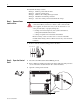
Step 3: Remove the
Existing Discharge
Resistors
Important:Mark all connections and wires before removal to avoid incorrect
wiring during reassembly.
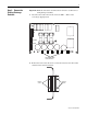
1. Disconnect the resistor wires from connectors XR-1…XR-5 on the
overvoltage clipping board.
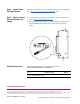
2. Remove the four screws that secure each of the resistors to the drive frame
and remove the resistors and wires.
XCD
X1UVW1
XUVW
F31 F21 F11
XR-5 XR-4 XR-3 XR-2 XR-1
C5gn C4blu C7gnC7blu
XR-6
Disconnect cables
from connectors
Remove
screws
Remove
screws