
Manual
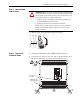
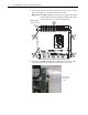
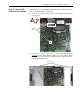

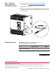
Table Of Contents
- Front Cover
- What This Kit Includes
- Tools That You Need
- What You Need to Do
- Step 1: Remove Power from the Drive
- Step 2: Remove the Protective Covers
- Step 3: Move the EMI Shield and Control Board
- Step 4: Remove the Existing Field Snubber Circuit Board
- Step 5: Install the New Field Snubber Circuit Board
- Step 6: Install the EMI Shield and Control Board
- Step 7: Replace the Protective Covers and Documenting the Change
- Related Documentation
- Pub. No. - Date
4 PowerFlex® DC Drive - Frame C Field Snubber Circuit Board
3. Loosen, but do not remove, the screws that secure the top cover to the
drive, then slide the cover up and off the drive chassis.
Important: The HIM assembly is connected via a cable to the Control
board and therefore will not pull free from the drive until
disconnected. See step 4 below for instructions.
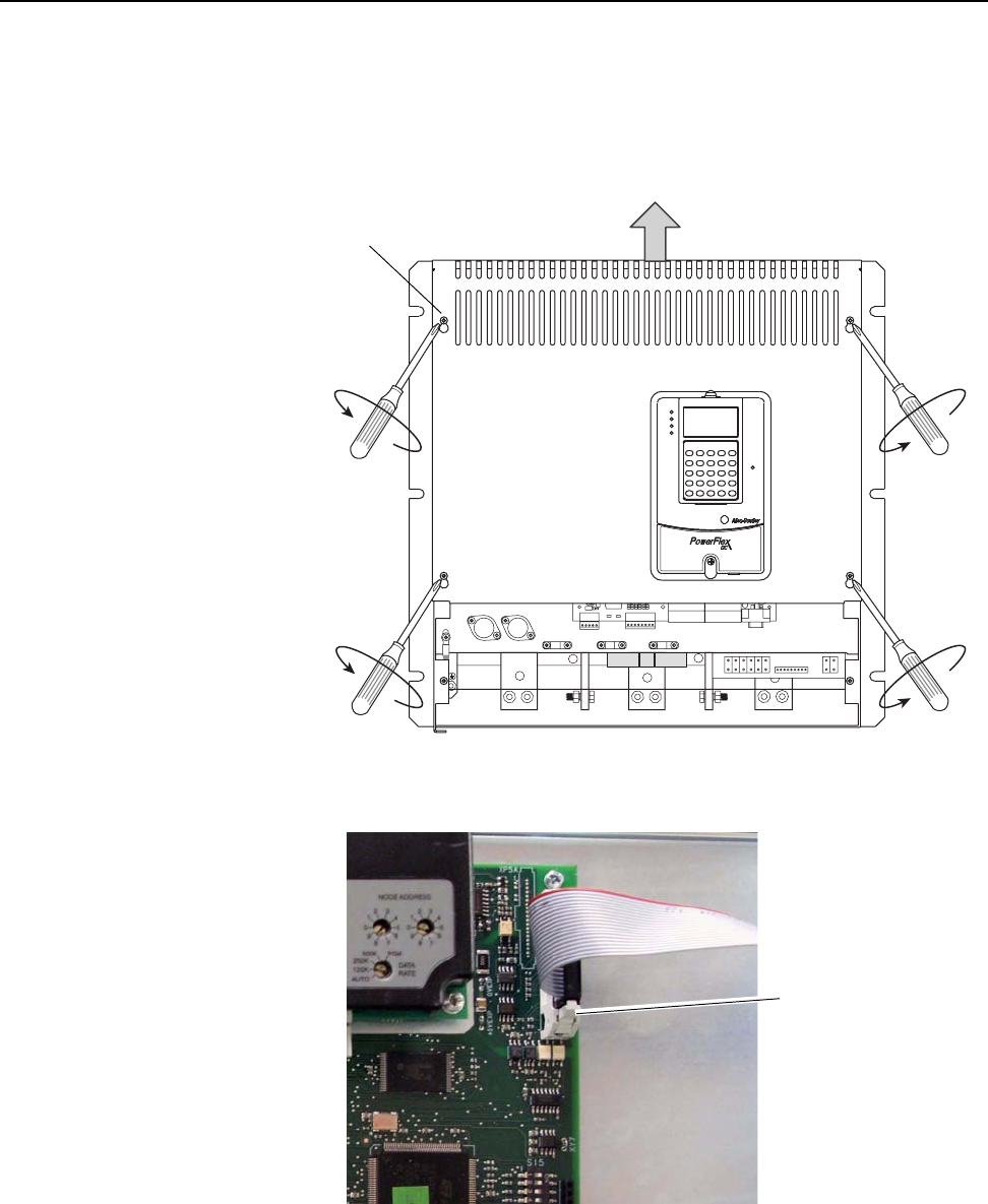
4. Disconnect the HIM Communication cable from the connector on the
upper right corner of the Control board and set the cover aside.
STS
PORT
MOD
NET A
NET B
FU1 FV1
U
V
C
D
W
Tightening torque:
1.5 N-m (13.3 lb.-in.)
Pull tabs out
to disconnect
cable.