
Manual

14 PowerFlex® DC Drive - Frame C AC Line Snubber Board and High Wattage Resistors
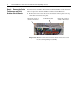
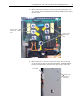
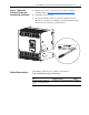
Step 6: Install the New AC
Line Snubber Board and
Resistors
Install the AC Line Snubber boards and Resistors in reverse order of
removal and detailed in Step 5: Remove the Existing AC Line Snubber
Circuit Board and Resistors on page 12.
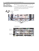
• Apply thermal grease to the bottom of the resistors before securing them
to the heatsink.
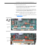
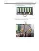
Step 7: Install the Pulse
Transformer and Field
Snubber Circuit Boards
Install the Pulse Transformer and Field Snubber boards in reverse order of
removal and detailed in Step 4: Remove the Pulse Transformer and Field
Snubber Circuit Boards on page 8.
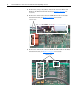
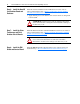
Step 8: Install the EMI
Shield and Control Board
Install the EMI Shield and Control board in reverse order of removal as
detailed in Step 3: Move the EMI Shield and Control Board
on page 5.
!
ATTENTION: Thermal grease must be applied to the bottom
of the resistors before securing them to the heatsink or damage to
the drive may occur.
!
ATTENTION: Each gate lead cable must be connected to the
exact connector from which it was removed on the Pulse
Transformer circuit board or damage to the drive may occur.