
Owner's manual

PowerFlex® DC Drive - Frame B Switching Power Supply Circuit Board 9
Step 4: Install the New
Switching Power Supply
Board
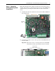
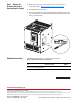
1. Install the new Switching Power Supply board in reverse order of
removal as detailed in Step 3: Remove the Existing Switching Power
Supply Board on page 5.
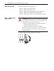
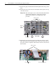
2. Replace the 16 Pin cable connected to connector XA on the Switching
Power Supply board with the new cable provided.
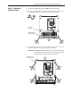
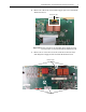
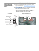
– Verify that the four plastic board stabilizers mounted on the top air
flow plate are placed one on either side of each of the Pulse
Transformer and Switching Power Supply boards.
One plastic stabilizer should be on either side of each boardAir flow plate
Plastic
stabilizers
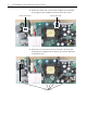
Top view of Pulse Transformer boardSide cut-away view
Pulse Transformer board
Switching Power Supply board