
Owner manual

Publication 20P-IN036B-EN-P - December 2009
Supersedes 20P-IN036A-EN-P - March 2009 Copyright © 2009 Rockwell Automation. All rights reserved. Printed in USA.
www.rockwellautomation.com
A
mericas:
Rockwell
Automation,
1201
South
Second
Street,
Milwaukee,
WI
53204-2496
USA,
Tel:
(1) 414.382.2000
,
Fax:
(1)
414.382.4444
Europe/Middle East/Africa:
Rockwell
Automation
SA/NV,
Vorstlaan/Boulevard
du Souverain
36,
1170 Brussels,
Belgium,
Tel:
(32) 2 663
0600,
Fax:
(32) 2 663 0640
A
sia
Pacific:
Rockwell
Automation
,
Level 14
,
Core F
,
C
y
ber
p
ort 3
,
100 C
y
ber
p
ort Road
,
Hon
g
Kon
g,
Tel:
(
852
)
2887 4788
,
Fax:
(
852
)
2508 1846
Power, Control and Information Solutions
1S7A25
2. At the top of the drive, remove the two fuses by inserting a screwdriver
in the slot on the top of the fuse, carefully pushing down and turning the
fuse counterclockwise. When the fuse holder releases, remove the
holder and fuse.
3. Insert the new fuses into the appropriate holders and replace the fuse
holder caps.
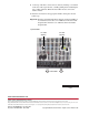
Important:For drives with Switching Power Supply circuit board SW2-32,
rev. H & below, insert the 3.15A 250V fuse in the fuse holder
designated F1. Insert the 2.5A 250V fuse in the fuse holder
designated F2.
Top View of Drive
Front of Drive
F1 = 3.15A
250V fuse
F2 = 2.5A
250V fuse