
Owner's manual

14 Rockwell Automation Publication 20P-IN009D-EN-P - February 2012
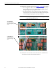
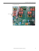
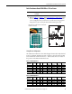
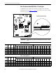
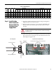
PowerFlex DC Drive Frame B Pulse Transformer Circuit Board
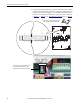
2. Connect the leads of the multimeter to pins 13 and 14 of connector XR on
the Pulse Transformer board (polarity is not important) and, using the TA
potentiometer on the lower right corner of the Pulse Transformer circuit
board, set the total resistance (RTA) to the appropriate value as indicated
in Ta b le 3 -
or Table 4 - in the Total Resistance Values section on page 15.
XP
1
X3
1
XSW
16
1
2
33
34
XR
TR2 TR1
XY
1
0V1
T04T01
T05T02
T06T03
T1
T4
T2 T5
T3 T6
K
G
KG04
K
G
KG01
K
G
KG05
K
G
KG02
K
G
KG06
K
G
KG03
K
G
KG4
K
G
KG1
K
G
KG5
K
G
KG2
K
G
KG6
K
G
KG3
XTA
1
TA
1
78 79 35 367576U2V2
UCVW
TA
1
X4
1
F2
F3
F1
1 . . . . . . . . . . . . . .13 . . . . . . . . . . . . . . . . . . . . 33
2 . . . . . . . . . . . . . 14 . . . . . . . . . . . . . . . . . . . 34
XR
=
The XR connector is located on the upper right
corner of the Pulse Transformer circuit board.
The TA potentiometer is located on the lower
right corner of the Pulse Transformer circuit
board next to the control power terminal block.