
Manual

PowerFlex® DC Drive - Frame B Bimetal Thermostat 15
Step 6: Install the Pulse
Transformer Board and
Switching Power Supply
Board
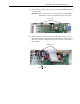
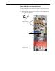
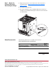
1. Install the Pulse Transformer board and Switching Power Supply board
in reverse order of removal as detailed in Step 3: Remove the Pulse
Transformer and Switching Power Supply Boards on page 5.
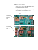
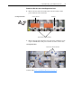
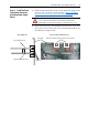
2. Verify that the four plastic board stabilizers mounted on the top air flow
plate are placed one on either side of each of the Pulse Transformer and
Switching Power Supply boards.
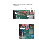
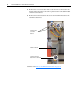
ATTENTION: Each gate lead cable must be connected to the
exact connector from which it was removed on the Pulse
Transformer circuit board or damage to the drive may occur.
One plastic stabilizer should be on either side of each boardAir flow plate
Plastic
stabilizers
Top view of Pulse Transformer boardSide cut-away view
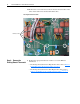
Pulse Transformer board
Switching Power Supply board