
Manual
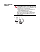
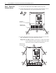
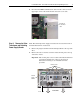
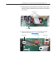
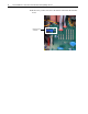
Table Of Contents
- Front Cover
- What This Kit Includes
- Tools That You Need
- What You Need to Do
- Step 1: Remove Power from the Drive
- Step 2: Remove the Protective Covers
- Step 3: Remove the Pulse Transformer and Switching Power Supply Boards
- Step 4: Remove the Field Circuit Board
- Step 5: Remove the Existing AC Line Snubber Board and Resistors
- Step 6: Install the New AC Line Snubber Board and Resistors
- Step 7: Install the Field Circuit Board
- Step 8: Install the Pulse Transformer and Switching Power Supply Boards
- Step 9: Replace the Protective Covers and Documenting the Change
- Related Documentation
- Publication 20P-IN015B-EN-P - December 2009
PowerFlex® DC Drive - Frame B AC Line Snubber Board and High Wattage Resistors 9
8. Remove the two screws that secure the air flow plate to the top of the
Pulse Transformer board and lift the plate off the drive chassis. The air
flow plate cannot be completely removed due to the fuse connections at
FU1 and FV1.
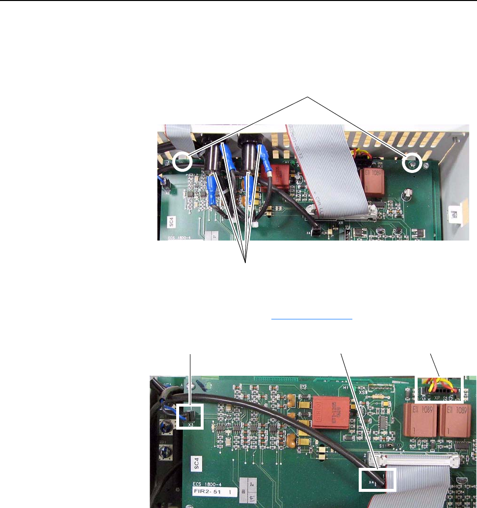
9. Remove the cables from connectors X3, X4 and XP on the Pulse
Transformer board (see Figure 1 on page 6
for location).
Remove screws
Fuse connections
Remove cableRemove cable Remove cable