
Manual
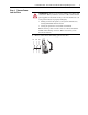
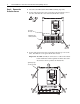
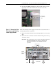
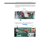
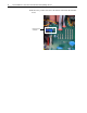
Table Of Contents
- Front Cover
- What This Kit Includes
- Tools That You Need
- What You Need to Do
- Step 1: Remove Power from the Drive
- Step 2: Remove the Protective Covers
- Step 3: Remove the Pulse Transformer and Switching Power Supply Boards
- Step 4: Remove the Field Circuit Board
- Step 5: Remove the Existing AC Line Snubber Board and Resistors
- Step 6: Install the New AC Line Snubber Board and Resistors
- Step 7: Install the Field Circuit Board
- Step 8: Install the Pulse Transformer and Switching Power Supply Boards
- Step 9: Replace the Protective Covers and Documenting the Change
- Related Documentation
- Publication 20P-IN015B-EN-P - December 2009
8 PowerFlex® DC Drive - Frame B AC Line Snubber Board and High Wattage Resistors
6. Carefully disconnect the cables from connectors XA, XR and XFCD at
the top of the Control board.
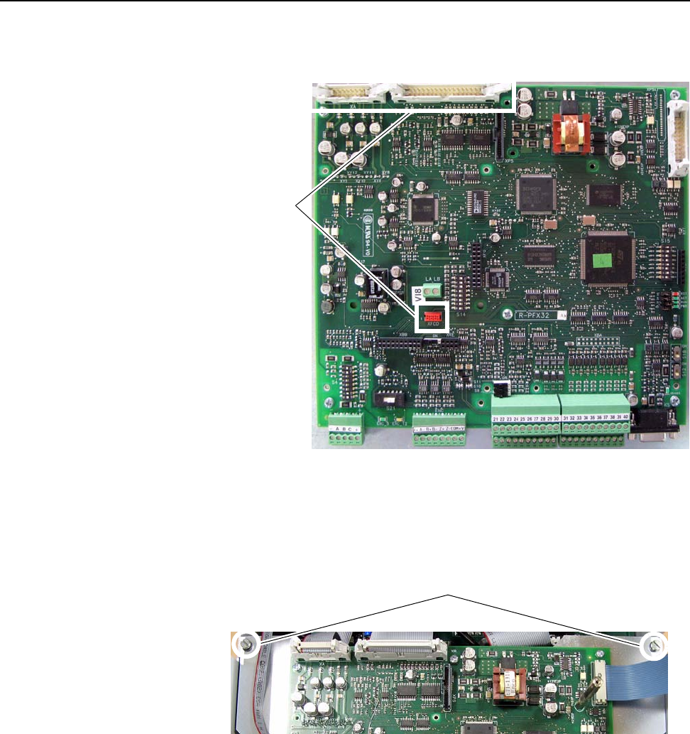
7. Loosen the two captive screws at the top of the Control EMI shield and
lower the shield.
Important: If the drive is not in a vertical position, the Control EMI
shield will not remain open without a means of restraint.
Disconnect
cables
Loosen screws