
Manual
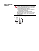
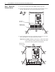
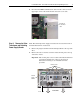
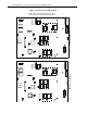
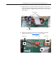
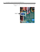
Table Of Contents
- Front Cover
- What This Kit Includes
- Tools That You Need
- What You Need to Do
- Step 1: Remove Power from the Drive
- Step 2: Remove the Protective Covers
- Step 3: Remove the Pulse Transformer and Switching Power Supply Boards
- Step 4: Remove the Field Circuit Board
- Step 5: Remove the Existing AC Line Snubber Board and Resistors
- Step 6: Install the New AC Line Snubber Board and Resistors
- Step 7: Install the Field Circuit Board
- Step 8: Install the Pulse Transformer and Switching Power Supply Boards
- Step 9: Replace the Protective Covers and Documenting the Change
- Related Documentation
- Publication 20P-IN015B-EN-P - December 2009
PowerFlex® DC Drive - Frame B AC Line Snubber Board and High Wattage Resistors 7
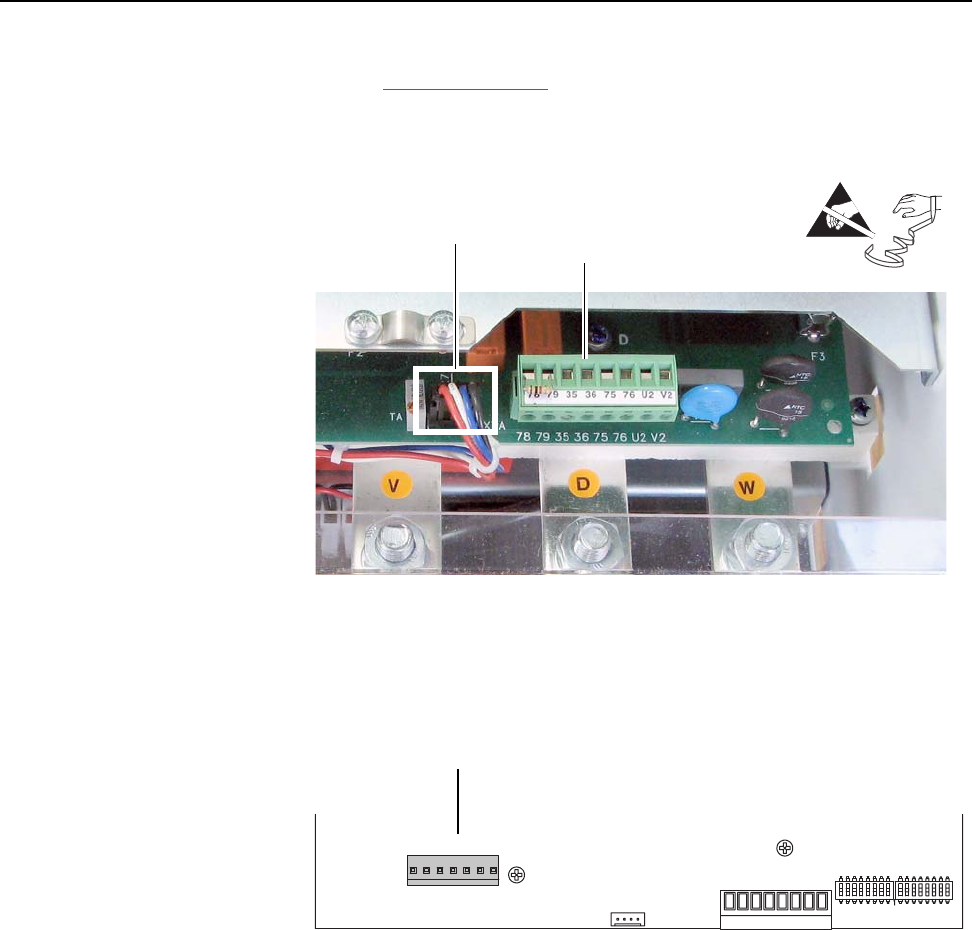
3. Remove the cable from connector XTA on the Pulse Transformer board
(see Figure 1 on page 6
for location).
4. Remove the plug-in terminals from the Control power block on the
Pulse Transformer board.
5. For Pulse Transformer boards with an armature voltage feedback
terminal block, FIR2-XX, rev. “N” and higher, remove the connector
from XCD_IO on the lower left corner of the board.
=
Remove cable Remove plug-in
terminals
XCD_IO
C
XTA
XM
D
78 79 35 36 75 76 U2 V2
S3 S4
1
Remove connector from XCD_IO