
Manual
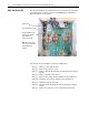
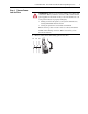
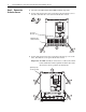
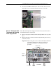
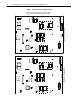
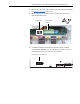
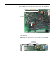
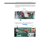
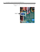
Table Of Contents
- Front Cover
- What This Kit Includes
- Tools That You Need
- What You Need to Do
- Step 1: Remove Power from the Drive
- Step 2: Remove the Protective Covers
- Step 3: Remove the Pulse Transformer and Switching Power Supply Boards
- Step 4: Remove the Field Circuit Board
- Step 5: Remove the Existing AC Line Snubber Board and Resistors
- Step 6: Install the New AC Line Snubber Board and Resistors
- Step 7: Install the Field Circuit Board
- Step 8: Install the Pulse Transformer and Switching Power Supply Boards
- Step 9: Replace the Protective Covers and Documenting the Change
- Related Documentation
- Publication 20P-IN015B-EN-P - December 2009
6 PowerFlex® DC Drive - Frame B AC Line Snubber Board and High Wattage Resistors
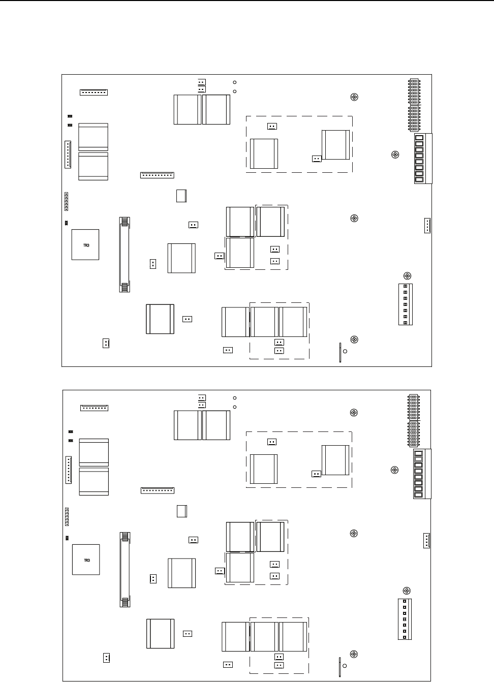
Figure 1 Pulse Transformer Circuit Board Layout
XSW1
XI2CA
X3
XP
TR2 TR1
XR
X4
XY
XCD_IO
TO5
TO3
TO6
TO1
TO4
TO2
KGO1
KGO4
KGO2
KGO5
KGO3
KGO6
T5
T3
T6
T1
T2
KG1
KG4
KG2
KG5
KG3
KG6
XCT
C
U
PE
PE1
V
XTA
XM
D
78 79 35 36 75 76 U2 V2
W
S3 S4
1U2
1V2
T4
1
XSW1
XI2CA
X3
XP
TR2 TR1
XR
X4
XY
XCD_IO
TO5
TO3
TO6
TO1
TO4
TO2
KGO1
KGO4
KGO2
KGO5
KGO3
KGO6
T5
T3
T6
T1
T2
KG1
KG4
KG2
KG5
KG3
KG6
XCT
C
U
PE
PE1
V
XTA
XM
D
78 79 35 36 75 76 U2 V2
W
S3 S4
1U2
1V2
T4
1
Components shown within dashed lines are only on
the Pulse Transformer board for regenerative drives.
FIR2-XX rev. “M” and lowerFIR2-XX rev. “N” and higher