
Manual
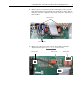
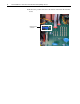
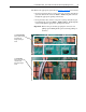
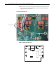
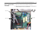
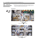
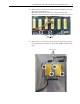
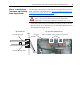
Table Of Contents
- Front Cover
- What This Kit Includes
- Tools That You Need
- What You Need to Do
- Step 1: Remove Power from the Drive
- Step 2: Remove the Protective Covers
- Step 3: Remove the Pulse Transformer and Switching Power Supply Boards
- Step 4: Remove the Field Circuit Board
- Step 5: Remove the Existing AC Line Snubber Board and Resistors
- Step 6: Install the New AC Line Snubber Board and Resistors
- Step 7: Install the Field Circuit Board
- Step 8: Install the Pulse Transformer and Switching Power Supply Boards
- Step 9: Replace the Protective Covers and Documenting the Change
- Related Documentation
- Publication 20P-IN015B-EN-P - December 2009
PowerFlex® DC Drive - Frame B AC Line Snubber Board and High Wattage Resistors 17
Step 8: Install the Pulse
Transformer and Switching
Power Supply Boards
Install the Pulse Transformer and Switching Power Supply boards in reverse
order of removal as detailed in Step 3: Remove the Pulse Transformer and
Switching Power Supply Boards on page 5.
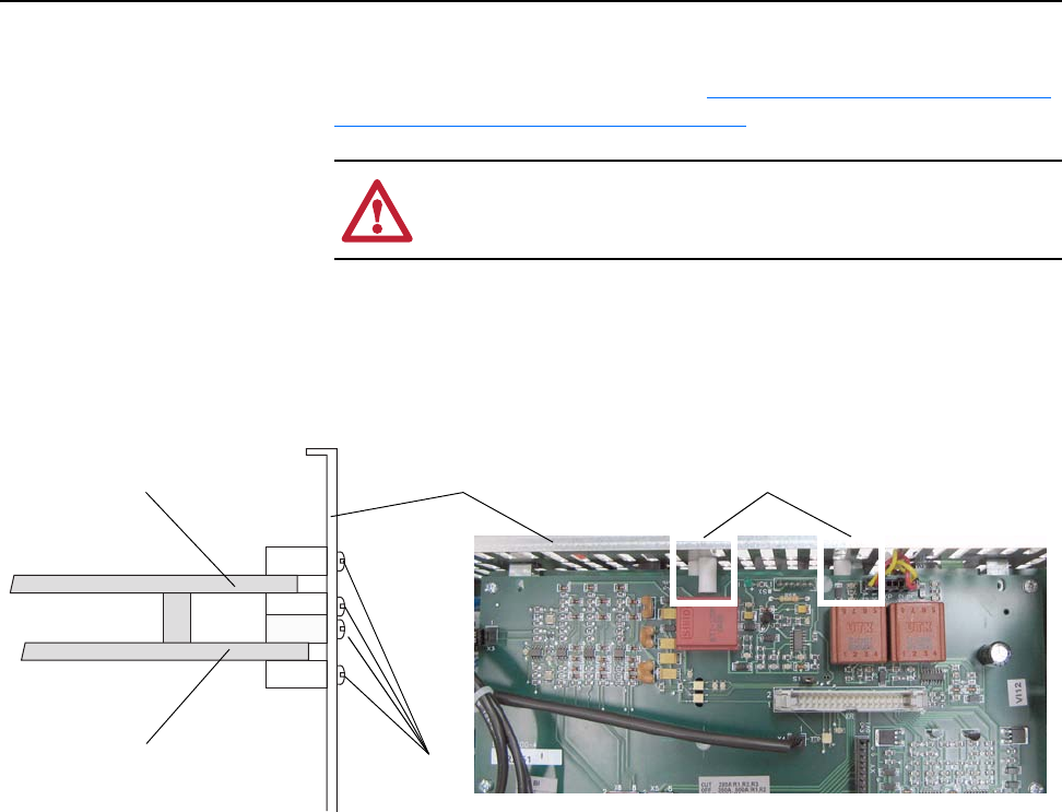
• Verify that the four plastic board stabilizers mounted on the top air flow
plate are placed one on either side of each of the Pulse Transformer and
Switching Power Supply boards.
ATTENTION: Each gate lead cable must be connected to the
exact connector from which it was removed on the Pulse
Transformer circuit board or damage to the drive may occur.
One plastic stabilizer should be on either side of each boardAir flow plate
Plastic
stabilizers
Top view of Pulse Transformer boardSide cut-away view
Pulse Transformer board
Switching Power Supply board