
Manual
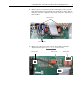
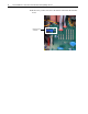
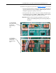
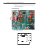
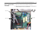
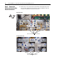
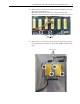
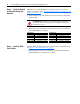
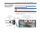
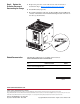
Table Of Contents
- Front Cover
- What This Kit Includes
- Tools That You Need
- What You Need to Do
- Step 1: Remove Power from the Drive
- Step 2: Remove the Protective Covers
- Step 3: Remove the Pulse Transformer and Switching Power Supply Boards
- Step 4: Remove the Field Circuit Board
- Step 5: Remove the Existing AC Line Snubber Board and Resistors
- Step 6: Install the New AC Line Snubber Board and Resistors
- Step 7: Install the Field Circuit Board
- Step 8: Install the Pulse Transformer and Switching Power Supply Boards
- Step 9: Replace the Protective Covers and Documenting the Change
- Related Documentation
- Publication 20P-IN015B-EN-P - December 2009
16 PowerFlex® DC Drive - Frame B AC Line Snubber Board and High Wattage Resistors
Step 6: Install the New AC
Line Snubber Board and
Resistors
Install the new AC Line Snubber board and resistors in reverse order of
removal as detailed in Step 5: Remove the Existing AC Line Snubber Board
and Resistors on page 14.
• Apply thermal grease to the bottom of the resistors before securing them
to the heatsink.
• Tightening torque for the bolts connecting the resistor wires and bus bars
to the SCR Modules is as follows:
Step 7: Install the Field
Circuit Board
Install the Field circuit board in reverse order of removal as detailed in Step
4: Remove the Field Circuit Board
on page 13.
• Tightening torque for the screws connected to the Field SCR and Dual
Diode Modules is 2.5
…4.0 N•m (22…35 lb•in).
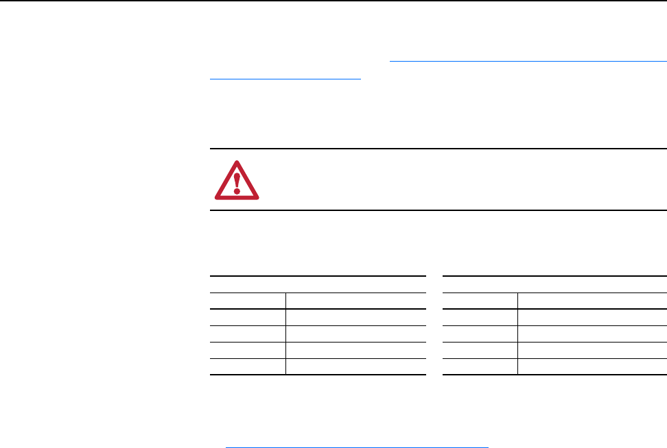
ATTENTION: Thermal grease must be applied to the bottom of
the resistors before securing them to the heatsink or damage to
the drive may occur.
230V AC Input 460V AC Input
Part Number Final Torque Part Number Final Torque
SK-20P-S7F48 4.5…5.5 N•m (40…48.7 lb•in) SK-20P-S7F78 4.5…5.5 N•m (40…48.7 lb•in)
SK-20P-S7F49 4.5…5.5 N•m (40…48.7 lb•in) SK-20P-S7F79 4.5…5.5 N•m (40…48.7 lb•in)
SK-20P-S7F42 11…13 N•m (97.4…115 lb•in) SK-20P-S7F41 11…13 N•m (97.4… 115 lb•in)
SK-20P-S727F 11… 13 N•m (97.4…115 lb•in) SK-20P-S737F 11…13 N•m (97.4…115 lb•in)