
Manual
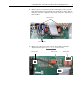
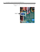
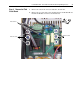
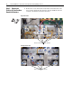
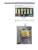
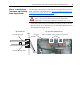
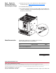
Table Of Contents
- Front Cover
- What This Kit Includes
- Tools That You Need
- What You Need to Do
- Step 1: Remove Power from the Drive
- Step 2: Remove the Protective Covers
- Step 3: Remove the Pulse Transformer and Switching Power Supply Boards
- Step 4: Remove the Field Circuit Board
- Step 5: Remove the Existing AC Line Snubber Board and Resistors
- Step 6: Install the New AC Line Snubber Board and Resistors
- Step 7: Install the Field Circuit Board
- Step 8: Install the Pulse Transformer and Switching Power Supply Boards
- Step 9: Replace the Protective Covers and Documenting the Change
- Related Documentation
- Publication 20P-IN015B-EN-P - December 2009
PowerFlex® DC Drive - Frame B AC Line Snubber Board and High Wattage Resistors 13
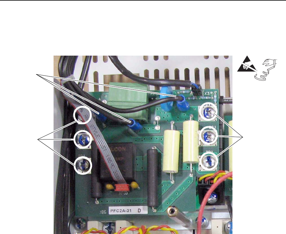
Step 4: Remove the Field
Circuit Board
1. Remove the wires from connectors UF, UF1, VF and VF1.
2. Remove the six screws that secure the Field board to the Field SCR and
Dual Diode Modules and remove the Field board.
=
Remove screws
Remove wires
Remove screws