
Owner manual

PowerFlex® DC Drive - Frame B AC Current Transducers 13
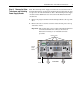
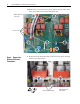
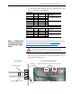
• Use the following table to determine the proper tightening torque for the
bus bars connected to the SCR Modules:
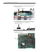
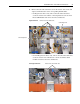
Step 6: Install the Pulse
Transformer Board and
Switching Power Supply
Board
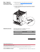
Install the Pulse Transformer board and Switching Power Supply board in
reverse order of removal as detailed in Step 3: Remove the Pulse
Transformer and Switching Power Supply Boards on page 5.
• Verify that the four plastic board stabilizers mounted on the top air flow
plate are placed one on either side of each of the Pulse Transformer and
Switching Power Supply boards.
230V AC Input
Drive Current
Rating Code DC Amps AC Line Amps HP Final Torque
146 146 119 40
4.5
…5.5 N•m (40…48.7 lb•in)180 180 147 50
218 218 178 60
265 265 217 75
11…13 N•m (97.4…115 lb•in)360 360 294 100
434 434 355 125
460V AC Input
Drive Current
Rating Code DC Amps AC Line Amps HP Final Torque
167 167 136.4 100
4.5
…5.5 N•m (40…48.7 lb•in)
207 207 169.1 125
250 250 204.3 150
11…13 N•m (97.4…115 lb•in)330 330 269.6 200
412 412 336.6 250
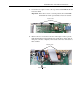
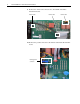
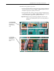
ATTENTION: Each gate lead cable must be connected to the
exact connector from which it was removed on the Pulse
Transformer circuit board or damage to the drive may occur.
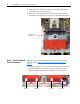
One plastic stabilizer should be on either side of each boardAir flow plate
Plastic
stabilizers
Top view of Pulse Transformer boardSide cut-away view
Pulse Transformer board
Switching Power Supply board