
Owner's manual
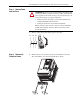
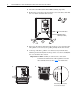
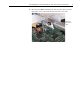
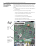
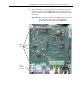
Table Of Contents
- Front Cover
- What This Kit Includes
- Tools That You Need
- What You Need to Do
- Step 1: Remove Power from the Drive
- Step 2: Remove the Protective Covers
- Step 3: Remove the Control EMI Shield and Control Board
- Step 4: Remove the Pulse Transformer and Switching Power Supply Boards
- Step 5: Remove the Power Traces Board
- Step 6: Remove the Existing SCR Modules
- Step 7: Install the New SCR Modules
- Step 8: Install the Power Traces Board
- Step 9: Install the Pulse Transformer and Switching Power Supply Boards
- Step 10: Install the Control EMI Shield and Control Board
- Step 11: Replace the Protective Covers and Documenting the Change
- Related Documentation
- Publication 20P-IN020B-EN-P - December 2009
8 PowerFlex® DC Drive - Frame A SCR Modules for Drives with a Power Traces Circuit Board
Step 4: Remove the Pulse
Transformer and Switching
Power Supply Boards
Note: The Switching Power Supply circuit board is secured to the back of
the Pulse Transformer circuit board.
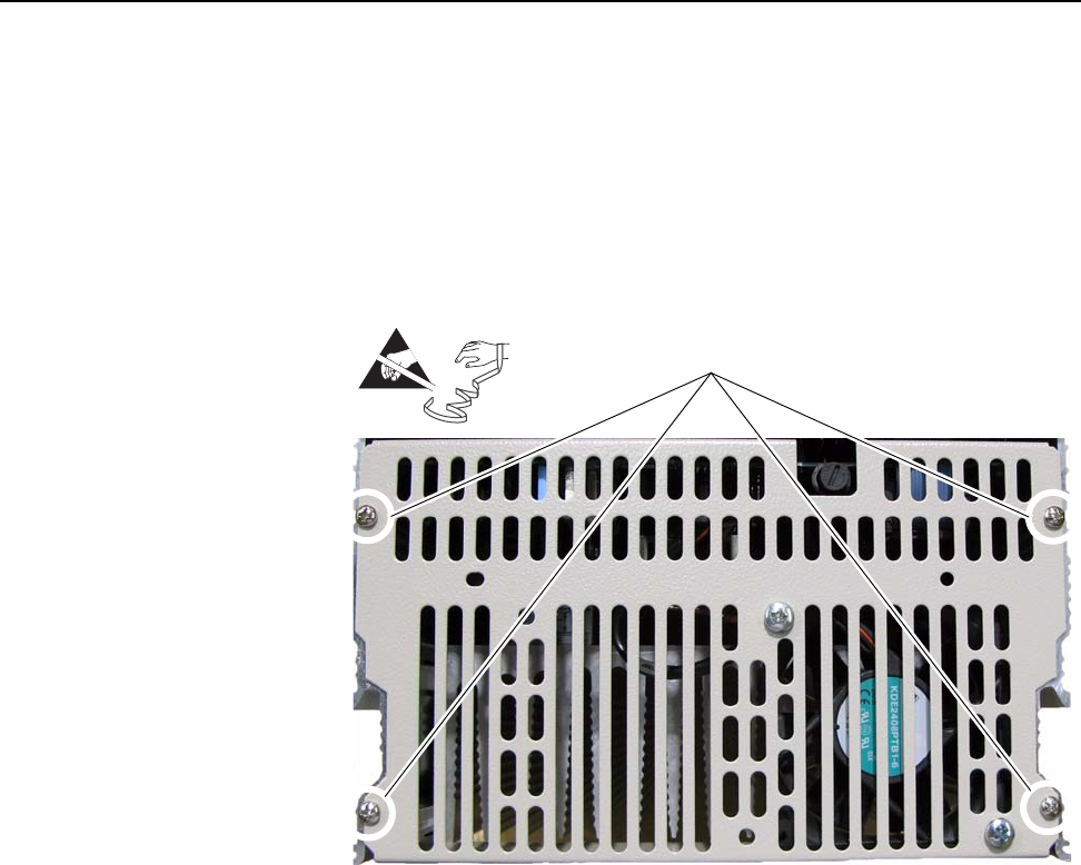
1. Remove the slotted air flow plate from the top of the drive.
– For 38A/10 HP and 55A/15 HP drives with 230V AC input and
35A/20 HP, 45A/25 HP, and 52A/30 HP drives with 460V AC
input, remove the four screws that secure the slotted air flow plate
to the top of the drive, remove the fan cable from connector XV on
the Switching Power Supply board and remove the plate.
=
Remove screws