
Owner's manual
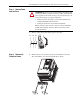
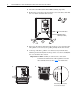
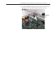
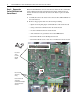
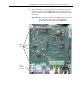
Table Of Contents
- Front Cover
- What This Kit Includes
- Tools That You Need
- What You Need to Do
- Step 1: Remove Power from the Drive
- Step 2: Remove the Protective Covers
- Step 3: Remove the Control EMI Shield and Control Board
- Step 4: Remove the Pulse Transformer and Switching Power Supply Boards
- Step 5: Remove the Power Traces Board
- Step 6: Remove the Existing SCR Modules
- Step 7: Install the New SCR Modules
- Step 8: Install the Power Traces Board
- Step 9: Install the Pulse Transformer and Switching Power Supply Boards
- Step 10: Install the Control EMI Shield and Control Board
- Step 11: Replace the Protective Covers and Documenting the Change
- Related Documentation
- Publication 20P-IN020B-EN-P - December 2009
6 PowerFlex® DC Drive - Frame A SCR Modules for Drives with a Power Traces Circuit Board
Step 3: Remove the
Control EMI Shield and
Control Board
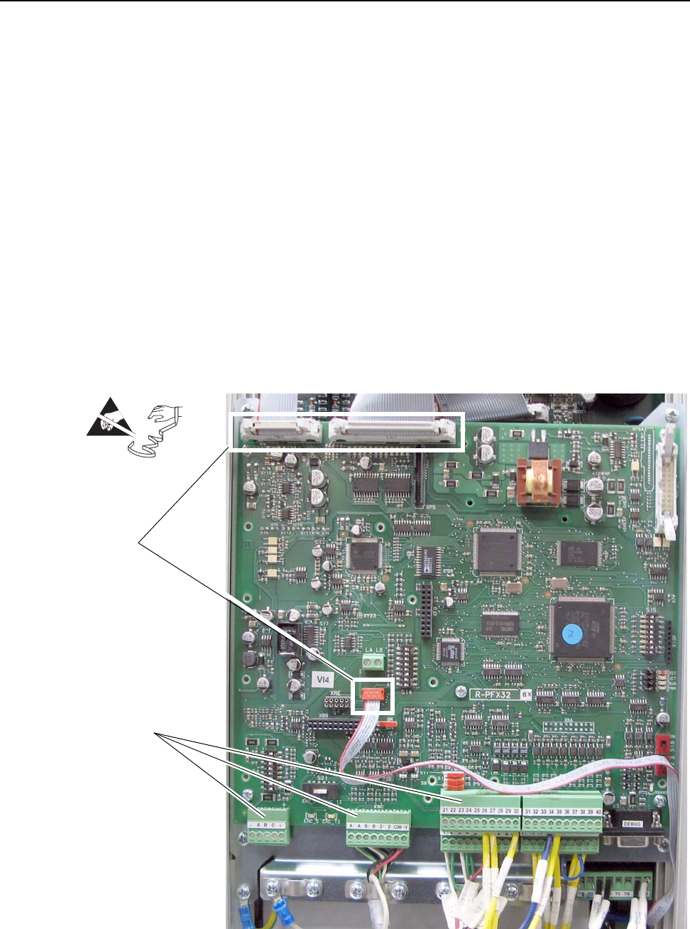
Note: The SCR Modules are located on the heat sink of the drive, behind the
Control, Pulse Transformer, Switching Power Supply and Power Traces
boards. All of these boards must be removed in order to replace the SCR
Modules.
1. Carefully disconnect the cables from connectors XA, XR and XFCD on
the Control board.
2. Remove all appropriate I/O and control wiring including:
– digital and analog I/O plug-in terminal blocks on the Control board
– analog tachometer terminal block on the Control board
– encoder terminal block on the Control board
– cable shields that are grounded to the Control EMI shield
– I/O terminal blocks on the I/O Expansion board
– I/O terminal blocks on the 115V AC to 24V DC I/O Converter board
=
Disconnect
cables
from XA,
XR and
XFCD
Disconnect I/O
and control
wiring
Note: Control board
shown with
Communication Adapter
and optional boards
removed.