
Owner's manual
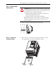
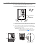
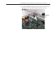
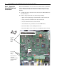
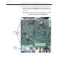
Table Of Contents
- Front Cover
- What This Kit Includes
- Tools That You Need
- What You Need to Do
- Step 1: Remove Power from the Drive
- Step 2: Remove the Protective Covers
- Step 3: Remove the Control EMI Shield and Control Board
- Step 4: Remove the Pulse Transformer and Switching Power Supply Boards
- Step 5: Remove the Power Traces Board
- Step 6: Remove the Existing SCR Modules
- Step 7: Install the New SCR Modules
- Step 8: Install the Power Traces Board
- Step 9: Install the Pulse Transformer and Switching Power Supply Boards
- Step 10: Install the Control EMI Shield and Control Board
- Step 11: Replace the Protective Covers and Documenting the Change
- Related Documentation
- Publication 20P-IN020B-EN-P - December 2009
4 PowerFlex® DC Drive - Frame A SCR Modules for Drives with a Power Traces Circuit Board
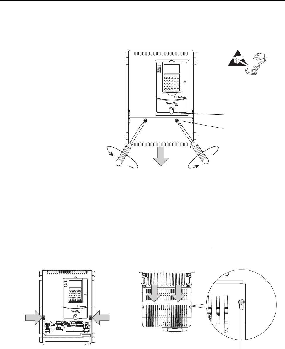
2. Disconnect the DPI cable from the HIM assembly (if present).
3. Remove the screws that secure the bottom cover to the drive, then slide
the cover down and off the drive chassis.
4. Press in on the sides at the bottom edge of the top cover and at the same
time pull the cover toward you to pull it partially off the drive chassis.
5. At the top of the drive, pull the cover forward, away from the drive,
until the pins fit in the keyhole in the top of the cover, then carefully lift
the cover off of the drive chassis.
Important:The HIM assembly is connected via a cable to the
Control board and therefore will not pull free from the
drive until disconnected. See page 5
for instructions.
=
Disconnect DPI cable
Tightening torque:
1.5 N•m (13.3 lb•in)
When metal pin fits in keyhole,
lift cover off drive chassis.
3.
4.