
Owner's manual
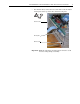
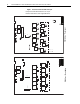
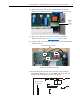
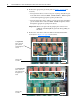
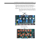
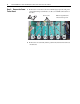
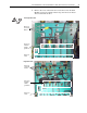
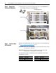
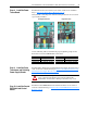
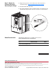
Table Of Contents
- Front Cover
- What This Kit Includes
- Tools That You Need
- What You Need to Do
- Step 1: Remove Power from the Drive
- Step 2: Remove the Protective Covers
- Step 3: Remove the Control EMI Shield and Control Board
- Step 4: Remove the Pulse Transformer and Switching Power Supply Boards
- Step 5: Remove the Power Traces Board
- Step 6: Remove the Existing SCR Modules
- Step 7: Install the New SCR Modules
- Step 8: Install the Power Traces Board
- Step 9: Install the Pulse Transformer and Switching Power Supply Boards
- Step 10: Install the Control EMI Shield and Control Board
- Step 11: Replace the Protective Covers and Documenting the Change
- Related Documentation
- Publication 20P-IN020B-EN-P - December 2009
16 PowerFlex® DC Drive - Frame A SCR Modules for Drives with a Power Traces Circuit Board
Step 6: Remove the
Existing SCR Modules
1. Remove the two screws and washers that secure each SCR Module to
the heatsink and remove the SCR Modules.
Step 7: Install the New
SCR Modules
Install the new SCR modules in reverse order of removal as detailed in Step
6: Remove the Existing SCR Modules
above.
Important:Verify that each SCR Module is orientated in the same position
as it was prior to removal.
Important:Thermal grease must be applied to the bottom of the SCR
modules before securing them to the heatsink.
Use the following table to determine the proper tightening torque for the
SCR Modules installed.
=
Regenerative drive
Non-Regenerative drive
Remove screws
Remove screws
230V AC Input 460V AC Input
Part Number Final Torque Part Number Final Torque
SK-20P-S7F44 2.5…4 N•m (22…35.4 lb•in) SK-20P-S7F73 2.5…4 N•m (22…35.4 lb•in)
SK-20P-S7F45 2.5…4 N•m (22…35.4 lb•in) SK-20P-S7F74 2.5…4 N•m (22…35.4 lb•in)