
Owner's manual
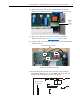
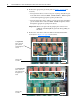
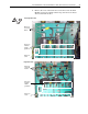
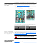
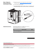
Table Of Contents
- Front Cover
- What This Kit Includes
- Tools That You Need
- What You Need to Do
- Step 1: Remove Power from the Drive
- Step 2: Remove the Protective Covers
- Step 3: Remove the Control EMI Shield and Control Board
- Step 4: Remove the Pulse Transformer and Switching Power Supply Boards
- Step 5: Remove the Power Traces Board
- Step 6: Remove the Existing SCR Modules
- Step 7: Install the New SCR Modules
- Step 8: Install the Power Traces Board
- Step 9: Install the Pulse Transformer and Switching Power Supply Boards
- Step 10: Install the Control EMI Shield and Control Board
- Step 11: Replace the Protective Covers and Documenting the Change
- Related Documentation
- Publication 20P-IN020B-EN-P - December 2009
14 PowerFlex® DC Drive - Frame A SCR Modules for Drives with a Power Traces Circuit Board
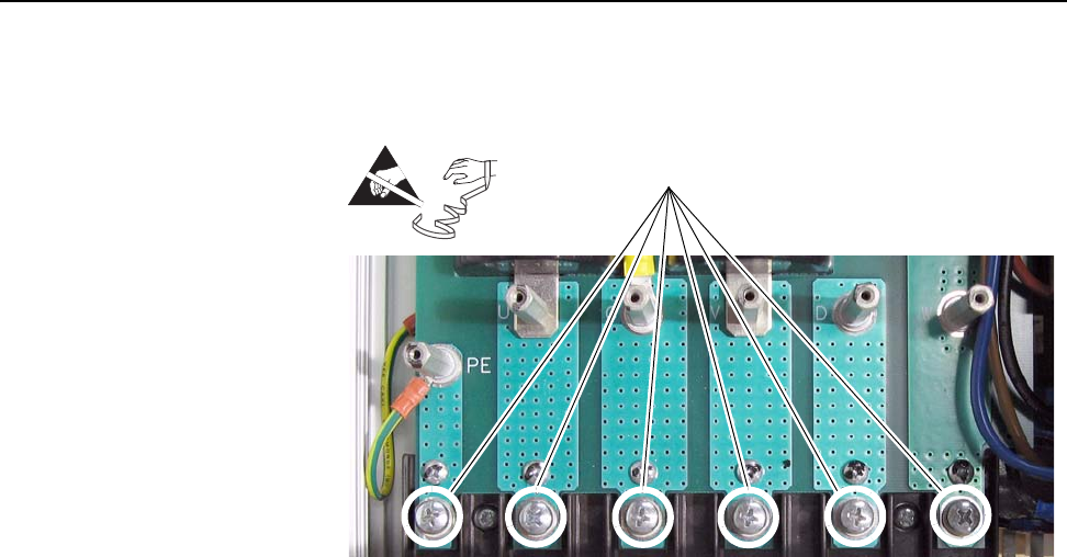
Step 5: Remove the Power
Traces Board
1. Remove the screws that secure the terminal lugs (if present) and power
and ground wiring to terminals U, V, W, C, D and PE at the bottom of
the drive.
2. Remove the six stand-offs (and the ground wire) from the Power Traces
circuit board.
=
Remove screws
Note: Non-regenerative drive
without terminal lugs shown.