
Owner's manual
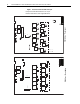
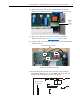
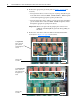
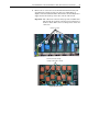
Table Of Contents
- Front Cover
- What This Kit Includes
- Tools That You Need
- What You Need to Do
- Step 1: Remove Power from the Drive
- Step 2: Remove the Protective Covers
- Step 3: Remove the Control EMI Shield and Control Board
- Step 4: Remove the Pulse Transformer and Switching Power Supply Boards
- Step 5: Remove the Power Traces Board
- Step 6: Remove the Existing SCR Modules
- Step 7: Install the New SCR Modules
- Step 8: Install the Power Traces Board
- Step 9: Install the Pulse Transformer and Switching Power Supply Boards
- Step 10: Install the Control EMI Shield and Control Board
- Step 11: Replace the Protective Covers and Documenting the Change
- Related Documentation
- Publication 20P-IN020B-EN-P - December 2009
12 PowerFlex® DC Drive - Frame A SCR Modules for Drives with a Power Traces Circuit Board
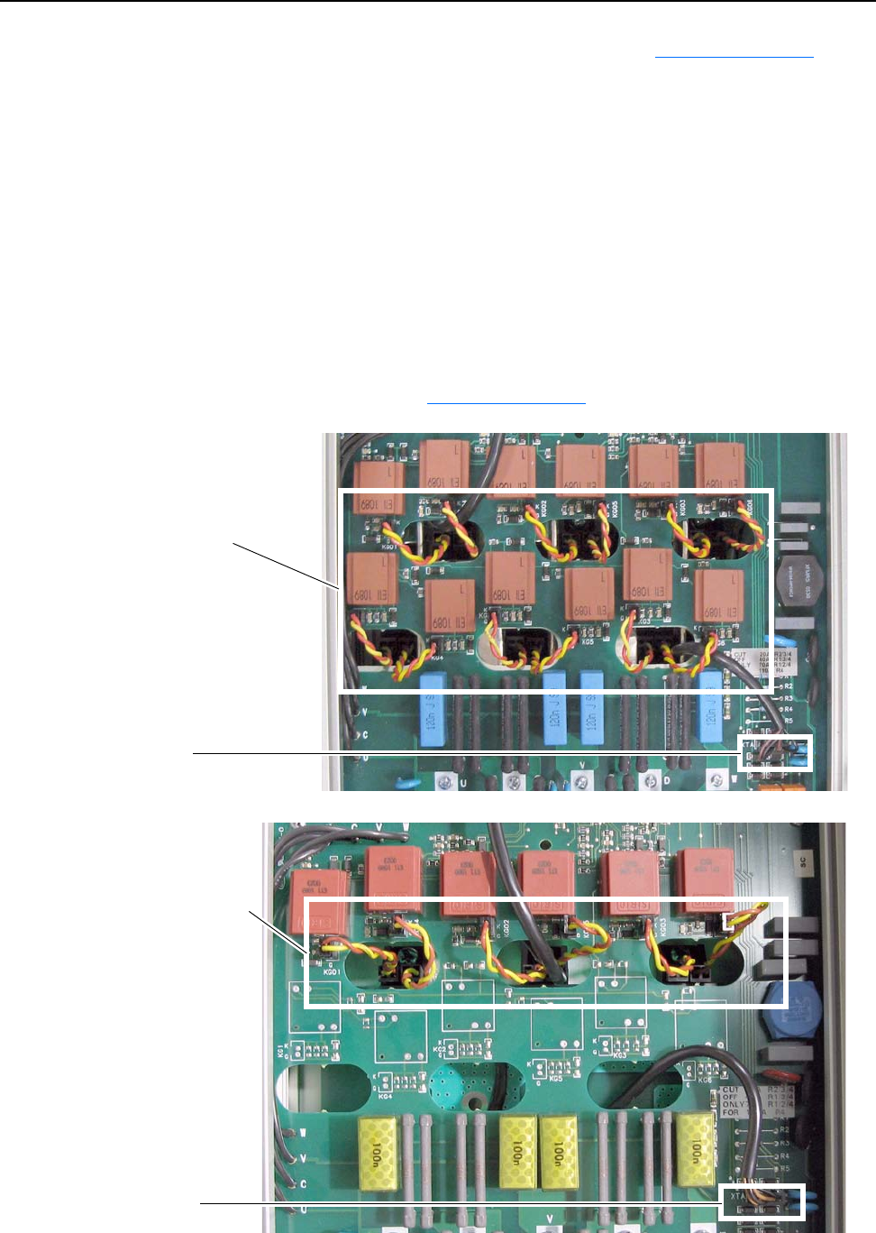
6. Remove the appropriate gate leads (refer to Figure 1 on page 10 for
location):
– For regenerative drives, remove each pair of (orange and yellow) gate
lead cables from connectors KG01…KG06 and KG1…KG6 and push
each lead through the appropriate opening in the board.
– For non-regenerative drives, remove each pair of (orange and yellow)
gate lead cables from connectors KG01…KG06 and push each lead
through the appropriate opening in the board.
Important: Remove the gate leads by grasping the connector and
pulling up. DO NOT pull the gate leads off by pulling on
the wires.
7. Remove the cable from connectors XTA on the Pulse Transformer
board (refer to Figure 1 on page 10
for location).
Remove cable
from XTA
For regenerative
drives, remove 12
gate leads and
push through holes
in board
Remove cable
from XTA
For non-regenerative
drives, remove six
gate leads and push
through holes in
board