
Owner's manual
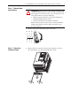
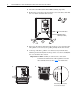
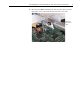
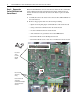
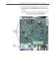
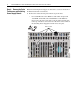
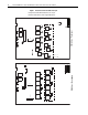
Table Of Contents
- Front Cover
- What This Kit Includes
- Tools That You Need
- What You Need to Do
- Step 1: Remove Power from the Drive
- Step 2: Remove the Protective Covers
- Step 3: Remove the Control EMI Shield and Control Board
- Step 4: Remove the Pulse Transformer and Switching Power Supply Boards
- Step 5: Remove the Power Traces Board
- Step 6: Remove the Existing SCR Modules
- Step 7: Install the New SCR Modules
- Step 8: Install the Power Traces Board
- Step 9: Install the Pulse Transformer and Switching Power Supply Boards
- Step 10: Install the Control EMI Shield and Control Board
- Step 11: Replace the Protective Covers and Documenting the Change
- Related Documentation
- Publication 20P-IN020B-EN-P - December 2009
10 PowerFlex® DC Drive - Frame A SCR Modules for Drives with a Power Traces Circuit Board
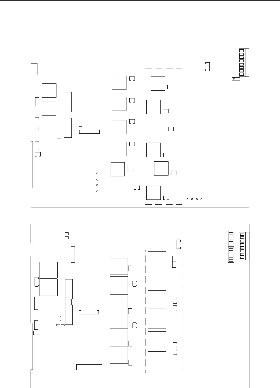
Figure 1 Pulse Transformer Circuit Board Layout
XP
11
XSW1
X3
1
XSW
16
1
2
33
34
XR
TR2 TR1
XY
1
0V1
T04
T01
T05T02 T06T03
T1
T4
T2
T5
T3
T6
K
G
KG04
K
G
KG01
K
G
KG05
K
G
KG02
K
G
KG06
K
G
KG03
K
G
KG4
K
G
KG1
K
G
KG5
K
G
KG2
K
G
KG6
K
G
KG3
XTA
1
TA
UCVW
W
V
C
U
X4
1
78 79 35 36 75 76 U2 V2
XSW1
XSW
X3
XP
TR2 TR1
XR
X4
XY
XCD_IO
TO1 TO4 TO2 TO5 TO3 TO6
KGO1 KGO4
KGO2
KGO5
TO1 TO4 TO2
KGO1 KGO4
KGO2
KGO5
KGO3
KGO6
T5 T3 T6T1 T4 T2
KG1 KG4 KG2 KG5
KG3 KG6
XTA
S4
S3
11
78 79 35 36 75 76 U2 V2
Components shown within dashed lines are only on
the Pulse Transformer board for regenerative drives.
FIR1-XX rev. “P” and lower
FIR1-XX rev. “Q” and higher