
User Manual
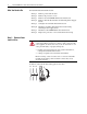
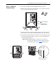
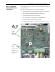
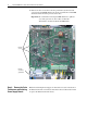
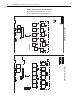
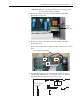
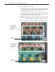
Table Of Contents
- Front Cover
- What This Kit Includes
- Tools That You Need
- What You Need to Do
- Step 1: Remove Power from the Drive
- Step 2: Remove the Protective Covers
- Step 3: Remove the Control EMI Shield and Control Board
- Step 4: Remove the Pulse Transformer and Switching Power Supply Boards
- Step 5: Configure the New Pulse Transformer Board
- Step 6: Install the New Pulse Transformer Board and Existing Switching Power Supply Board
- Step 7: Install the Control EMI Shield and Control Board
- Step 8: Replace the Protective Covers and Documenting the Change
- Related Documentation
- Publication 20P-IN008B-EN-P - December 2
PowerFlex® DC Drive - Frame A Pulse Transformer Circuit Board 9
Important: Mark all connections and wires before removal to avoid
incorrect wiring during reassembly.
2. Remove the plug-in control power terminal block from the Pulse
Transformer circuit board.
3. Remove the cables from connectors X3, X4 and XP on the Pulse
Transformer board.
Note: Connector X4 contains a jumper for drives without a fan - leave in
place.
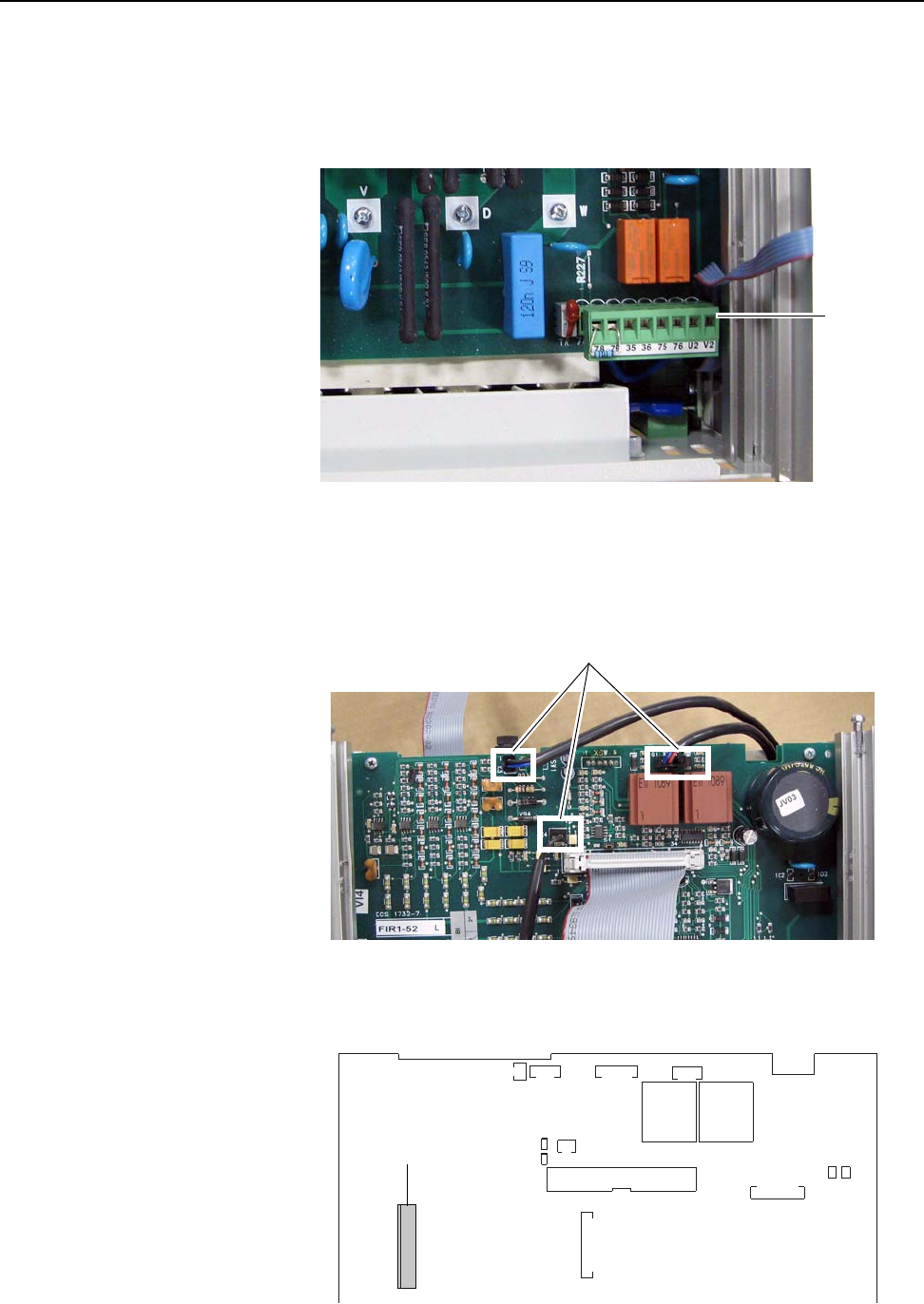
4. For Pulse Transformer boards with an armature voltage feedback
terminal block, FIR1-XX, rev “Q” and higher, remove the connector
from XCD_IO on the upper left corner of the board.
Remove
plug-in
terminal block
Remove cables from X3, X4 and XP
XSW1
XSW
X3
XP
TR2 TR1
XR
X4
XY
XCD_IO
Remove connector
from XCD_IO