
User Manual
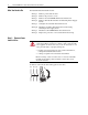
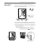
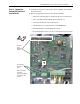
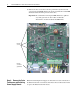
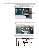
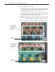
Table Of Contents
- Front Cover
- What This Kit Includes
- Tools That You Need
- What You Need to Do
- Step 1: Remove Power from the Drive
- Step 2: Remove the Protective Covers
- Step 3: Remove the Control EMI Shield and Control Board
- Step 4: Remove the Pulse Transformer and Switching Power Supply Boards
- Step 5: Configure the New Pulse Transformer Board
- Step 6: Install the New Pulse Transformer Board and Existing Switching Power Supply Board
- Step 7: Install the Control EMI Shield and Control Board
- Step 8: Replace the Protective Covers and Documenting the Change
- Related Documentation
- Publication 20P-IN008B-EN-P - December 2
6 PowerFlex® DC Drive - Frame A Pulse Transformer Circuit Board
3. Remove the five screws that secure the ground wire (in the lower left
corner) and Control EMI shield to the chassis and slide the Control EMI
shield and Control board up and out of the drive.
Important:Be careful when removing the EMI shield not to pull free
any of the gate leads or other cables on the Pulse
Transformer circuit board below the EMI shield.
Step 4: Remove the Pulse
Transformer and Switching
Power Supply Boards
Note: The Switching Power Supply circuit board is located on the back of
the Pulse Transformer circuit board. You must remove both boards in order
to replace the Pulse Transformer board.
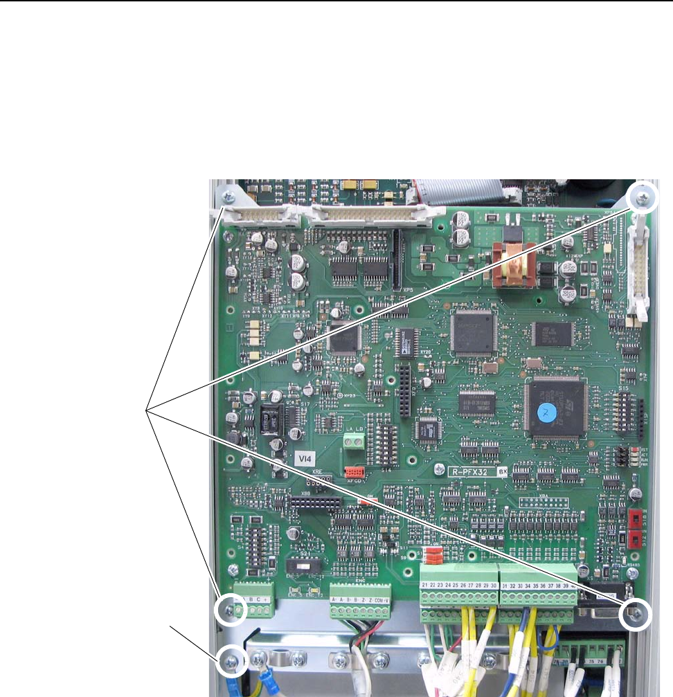
Remove
screws
Remove
screw and
ground wire