
User Manual
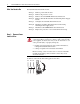
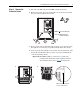
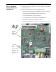
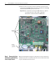
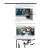
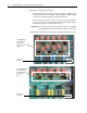
Table Of Contents
- Front Cover
- What This Kit Includes
- Tools That You Need
- What You Need to Do
- Step 1: Remove Power from the Drive
- Step 2: Remove the Protective Covers
- Step 3: Remove the Control EMI Shield and Control Board
- Step 4: Remove the Pulse Transformer and Switching Power Supply Boards
- Step 5: Configure the New Pulse Transformer Board
- Step 6: Install the New Pulse Transformer Board and Existing Switching Power Supply Board
- Step 7: Install the Control EMI Shield and Control Board
- Step 8: Replace the Protective Covers and Documenting the Change
- Related Documentation
- Publication 20P-IN008B-EN-P - December 2
PowerFlex® DC Drive - Frame A Pulse Transformer Circuit Board 5
Step 3: Remove the
Control EMI Shield and
Control Board
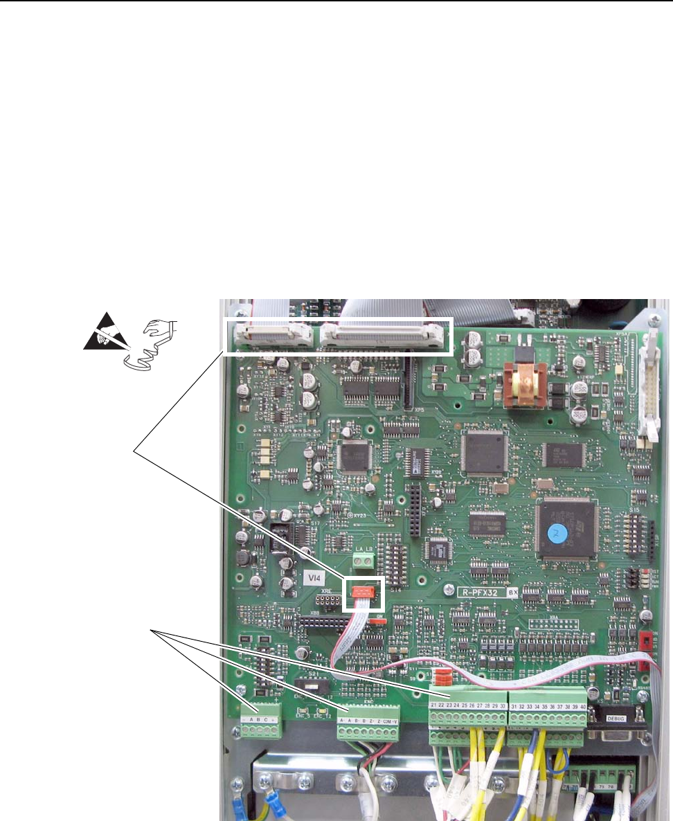
1. Carefully disconnect the cables from connectors XFCD, XA and XR on
the Control board.
2. Remove all appropriate I/O and control wiring including:
– digital and analog I/O plug-in terminal blocks on the Control board
– analog tachometer terminal block on the Control board
– encoder terminal block on the Control board
– cable shields that are grounded to the Control EMI shield
– I/O terminal blocks on the I/O Expansion board
– I/O terminal blocks on the 115V AC to 24V DC I/O Converter board
=
Disconnect
cables
XFCD, XA,
and XR
Disconnect I/O
and control
wiring
Note: Control board
shown with
Communication Adapter
and optional boards
removed.