
User Manual
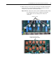
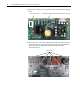
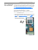
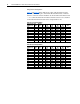
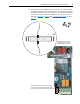
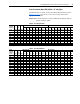
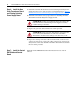
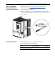

Table Of Contents
- Front Cover
- What This Kit Includes
- Tools That You Need
- What You Need to Do
- Step 1: Remove Power from the Drive
- Step 2: Remove the Protective Covers
- Step 3: Remove the Control EMI Shield and Control Board
- Step 4: Remove the Pulse Transformer and Switching Power Supply Boards
- Step 5: Configure the New Pulse Transformer Board
- Step 6: Install the New Pulse Transformer Board and Existing Switching Power Supply Board
- Step 7: Install the Control EMI Shield and Control Board
- Step 8: Replace the Protective Covers and Documenting the Change
- Related Documentation
- Publication 20P-IN008B-EN-P - December 2
PowerFlex® DC Drive - Frame A Pulse Transformer Circuit Board 19
Step 8: Replace the
Protective Covers and
Documenting the Change
1. Replace the protective covers in the reverse order of removal as
described in Step 2: Remove the Protective Covers
on page 3.
2. Install the DPI cable (if present).
3. Record the installation of the new Pulse Transformer board and date of
installation on the Field Installed Option label on the side of the drive (as
shown below).
Related Documentation
Allen-Bradley publications are available on the internet at
www.rockwellautomation.com/literature.
For . . . Read this document
Publication
Number
In depth information regarding the
operation of PowerFlex Digital DC drives
User Manual - PowerFlex Digital DC Drives 20P-UM001…