
User Manual
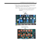
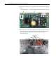
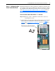
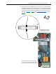

Table Of Contents
- Front Cover
- What This Kit Includes
- Tools That You Need
- What You Need to Do
- Step 1: Remove Power from the Drive
- Step 2: Remove the Protective Covers
- Step 3: Remove the Control EMI Shield and Control Board
- Step 4: Remove the Pulse Transformer and Switching Power Supply Boards
- Step 5: Configure the New Pulse Transformer Board
- Step 6: Install the New Pulse Transformer Board and Existing Switching Power Supply Board
- Step 7: Install the Control EMI Shield and Control Board
- Step 8: Replace the Protective Covers and Documenting the Change
- Related Documentation
- Publication 20P-IN008B-EN-P - December 2

18 PowerFlex® DC Drive - Frame A Pulse Transformer Circuit Board
Step 6: Install the New
Pulse Transformer Board
and Existing Switching
Power Supply Board
1. Install the new Pulse Transformer board and existing Switching Power
Supply board in reverse order of removal as detailed in Step 4: Remove
the Pulse Transformer and Switching Power Supply Boards on page 6.
2. Install the new Isolation sheet (if present) before installing the Pulse
Transformer and Switching Power Supply boards.
3. Replace the gate lead cables with the new cables provided.
4. Inspect the existing connection cables for burn marks, cracks or loose
connectors. If necessary, replace the cables connected to connector X3,
X4 (for drives with a fan) and XP on the Pulse Transformer board with
the new cables provided.
Step 7: Install the Control
EMI Shield and Control
Board
Install the Control EMI Shield and Control board in reverse order of
removal.
ATTENTION: Failure to install the Isolation sheet below the
Pulse Transformer and Switching Power Supply boards may
result in damage to the drive.
ATTENTION: Each gate lead cable must be connected to the
exact connector from which it was removed on the Pulse
Transformer circuit board or damage to the drive may occur.