
User Manual
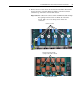
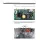
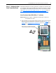
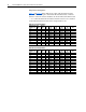
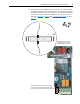
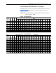
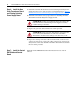

Table Of Contents
- Front Cover
- What This Kit Includes
- Tools That You Need
- What You Need to Do
- Step 1: Remove Power from the Drive
- Step 2: Remove the Protective Covers
- Step 3: Remove the Control EMI Shield and Control Board
- Step 4: Remove the Pulse Transformer and Switching Power Supply Boards
- Step 5: Configure the New Pulse Transformer Board
- Step 6: Install the New Pulse Transformer Board and Existing Switching Power Supply Board
- Step 7: Install the Control EMI Shield and Control Board
- Step 8: Replace the Protective Covers and Documenting the Change
- Related Documentation
- Publication 20P-IN008B-EN-P - December 2

PowerFlex® DC Drive - Frame A Pulse Transformer Circuit Board 17
Pulse Transformer Board FIR1-XX Rev. “Q” and Higher
Set DIP switches S3 and S4, located on the Pulse Transformer board (see
Figure 1 on page 8
for location), to the correct settings based on the
appropriate table below.
Important:A blank cell below a switch in Tables E and F below indicate
that the setting is “OFF”.
Table E 230V AC Input Drives
Table F 460V AC Input Drives
Drive
Current
Rating
Code
DC
Amps
AC
Line
Amps HP
DIP Switch S3 DIP Switch S4
S3-1 S3-2 S3-3 S3-4 S3-5 S3-6 S3-7 S3-8 S4-1 S4-2 S4-3 S4-4 S4-5 S4-6 S4-7 S4-8
7P0 7 5.7 1.5 ON ON ON
9P0 9 7.4 2 ON ON ON
012 12 9.8 3 ON ON ON
020 20 16 5 ON ON ON
029 29 24 7.5 ON ON ON
038 38 31 10 ON ON
055 55 45 15 ON ON ON ON
073 73 60 20 ONONONON
093 93 76 25 ON ON ON ON
110 110 90 30 ON ON ON ON
Drive
Current
Rating
Code
DC
Amps
AC
Line
Amps HP
DIP Switch S3 DIP Switch S4
S3-1 S3-2 S3-3 S3-4 S3-5 S3-6 S3-7 S3-8 S4-1 S4-2 S4-3 S4-4 S4-5 S4-6 S4-7 S4-8
4P1 4.1 3.3 2 ON ON ON
6P0 6 4.9 3 ON ON ON
010 10 8.2 5 ON ON ON
014 14 11.4 7.5 ON ON ON
019 19 15.510ONONON
027 27 22.1 15 ON ON ON
035 35 28.6 20 ON ON ON
045 45 36.825 ONON ONON
052 52 42.530 ON ONONON
073 73 59.640 ONONONON
086 86 70.3 50 ON ON ON
100 100 81.7 60 ON ON ON ON
129 129 105.4 75 ON ON ON ON