
User Manual
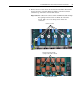
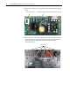
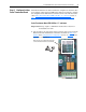
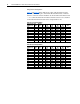
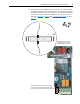
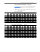
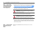
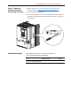

Table Of Contents
- Front Cover
- What This Kit Includes
- Tools That You Need
- What You Need to Do
- Step 1: Remove Power from the Drive
- Step 2: Remove the Protective Covers
- Step 3: Remove the Control EMI Shield and Control Board
- Step 4: Remove the Pulse Transformer and Switching Power Supply Boards
- Step 5: Configure the New Pulse Transformer Board
- Step 6: Install the New Pulse Transformer Board and Existing Switching Power Supply Board
- Step 7: Install the Control EMI Shield and Control Board
- Step 8: Replace the Protective Covers and Documenting the Change
- Related Documentation
- Publication 20P-IN008B-EN-P - December 2
PowerFlex® DC Drive - Frame A Pulse Transformer Circuit Board 15
2. Connect the leads of a multimeter to pins 13 and 14 of connector XR on
the Pulse Transformer circuit board (polarity is not important) and, using
the TA potentiometer on the lower right corner of the Pulse Transformer
circuit board, set the total resistance (RTA) to the appropriate value as
indicated in Table C
or Table D in the Total Resistance Values section on
page 16
.
1 . . . . . . . . . . . . . .13 . . . . . . . . . . . . . . . . . . . . 33
2 . . . . . . . . . . . . . 14 . . . . . . . . . . . . . . . . . . . 34
XR
=
The XR connector is located on
the upper right corner of the
Pulse Transformer circuit board.
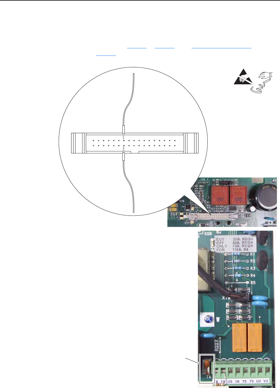
The TA potentiometer is located on the lower right
corner of the Pulse Transformer circuit board next
to the control power terminal block. Shown sealed.