
User Manual
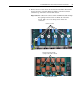
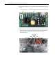
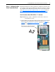
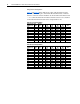
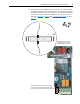
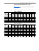
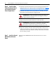

Table Of Contents
- Front Cover
- What This Kit Includes
- Tools That You Need
- What You Need to Do
- Step 1: Remove Power from the Drive
- Step 2: Remove the Protective Covers
- Step 3: Remove the Control EMI Shield and Control Board
- Step 4: Remove the Pulse Transformer and Switching Power Supply Boards
- Step 5: Configure the New Pulse Transformer Board
- Step 6: Install the New Pulse Transformer Board and Existing Switching Power Supply Board
- Step 7: Install the Control EMI Shield and Control Board
- Step 8: Replace the Protective Covers and Documenting the Change
- Related Documentation
- Publication 20P-IN008B-EN-P - December 2
PowerFlex® DC Drive - Frame A Pulse Transformer Circuit Board 13
Step 5: Configure the New
Pulse Transformer Board
The Pulse Transformer circuit board must be configured to match the drive
size (armature output current and HP rating). The steps required to complete
the configuration are different based on the revision code of the board. See
either, Pulse Transformer Board FIR1-XX Rev. “P” and Lower
below, or
Pulse Transformer Board FIR1-XX Rev. “Q” and Higher
on page 17.
Pulse Transformer Board FIR1-XX Rev. “P” and Lower
Important:This step requires a multimeter that measures resistance to
thousandths of an ohm.
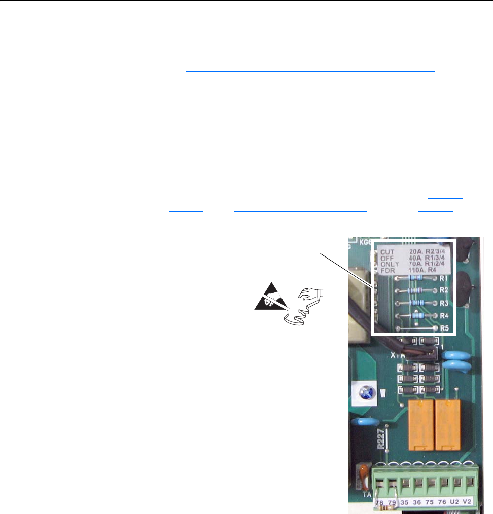
1. Cut and remove the appropriate sizing resistor(s) (if necessary) from the
Pulse Transformer board based on the drive size. Refer to Table A
or
Table B
in the Sizing Resistor Configuration section on page 14 for the
appropriate configuration.
=
Sizing resistors are located on the lower right
corner of the Pulse Transformer circuit board.